
Hot coating device for accelerating cooling

An accelerated cooling and thermal coating technology, applied in spraying devices, spray booths, etc., can solve problems such as threats to the health of workers, reduced work efficiency, and severe odor of spraying devices

Inactive Publication Date: 2019-03-08
江苏纵湖涂装设备产业研究院有限公司
View PDF0 Cites 1 Cited by
  • Summary
  • Abstract
  • Description
  • Claims
  • Application Information

AI Technical Summary

Problems solved by technology

[0002] The thermal coating device is a kind of material that sprays heat on some objects that need to be coated, so that the outer surface of the object can be protected. There are some problems in the current thermal coating device. When painting, the object is only placed on the storage plate with through holes, so that the coated side of the object is in contact with the storage plate to cause the material to be rubbed, and it needs to be sprayed again. The current thermal coating device is inside There is no mechanical cooling of the object, which reduces the work efficiency, and the current thermal spraying device does not take ventilation inside, which makes the internal smell of the spraying device particularly serious, and it is easy to cause a threat to the health of the workers. Therefore, a Accelerated Cooling Thermal Coating Unit

Method used

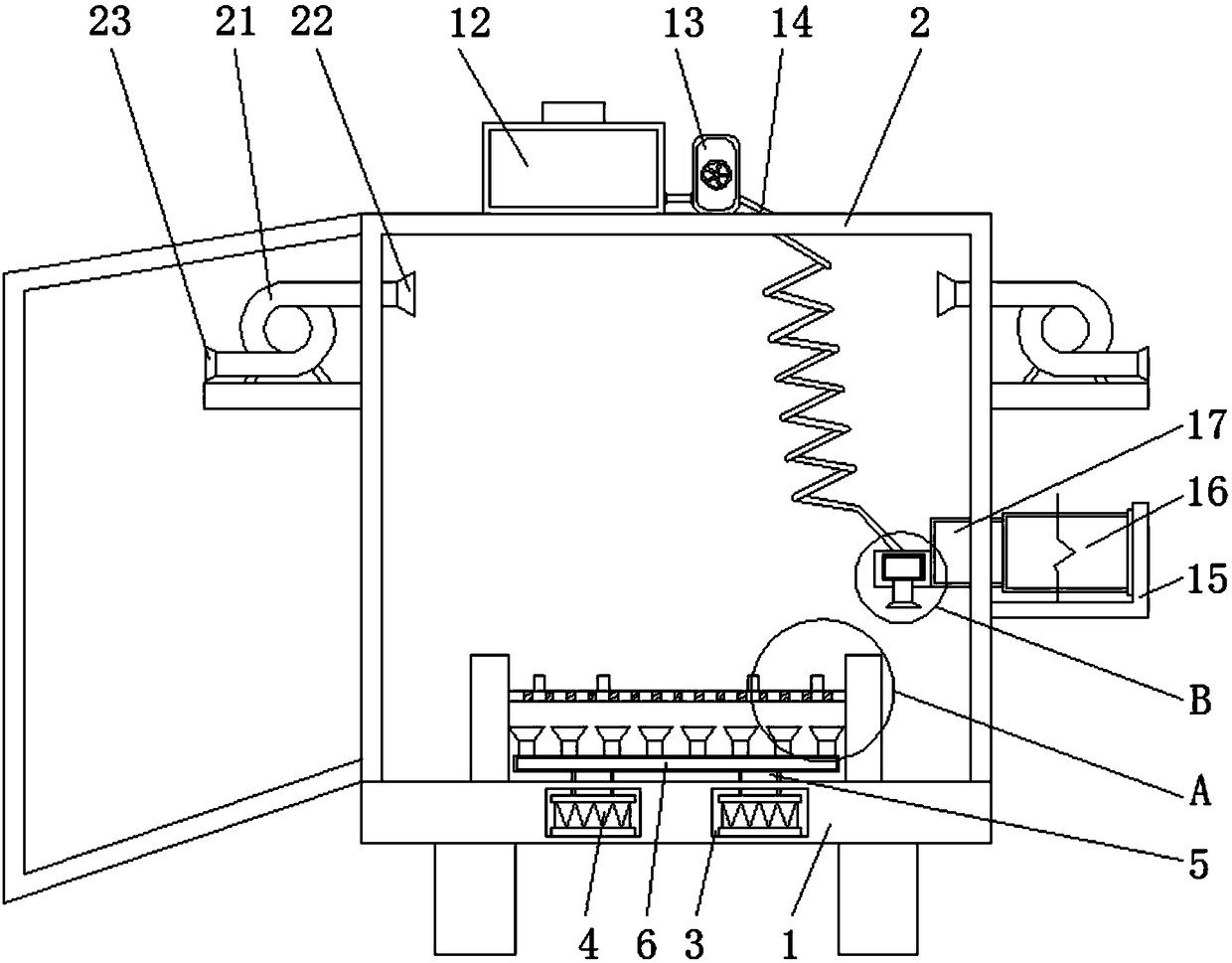
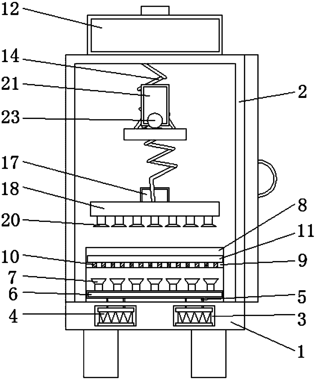
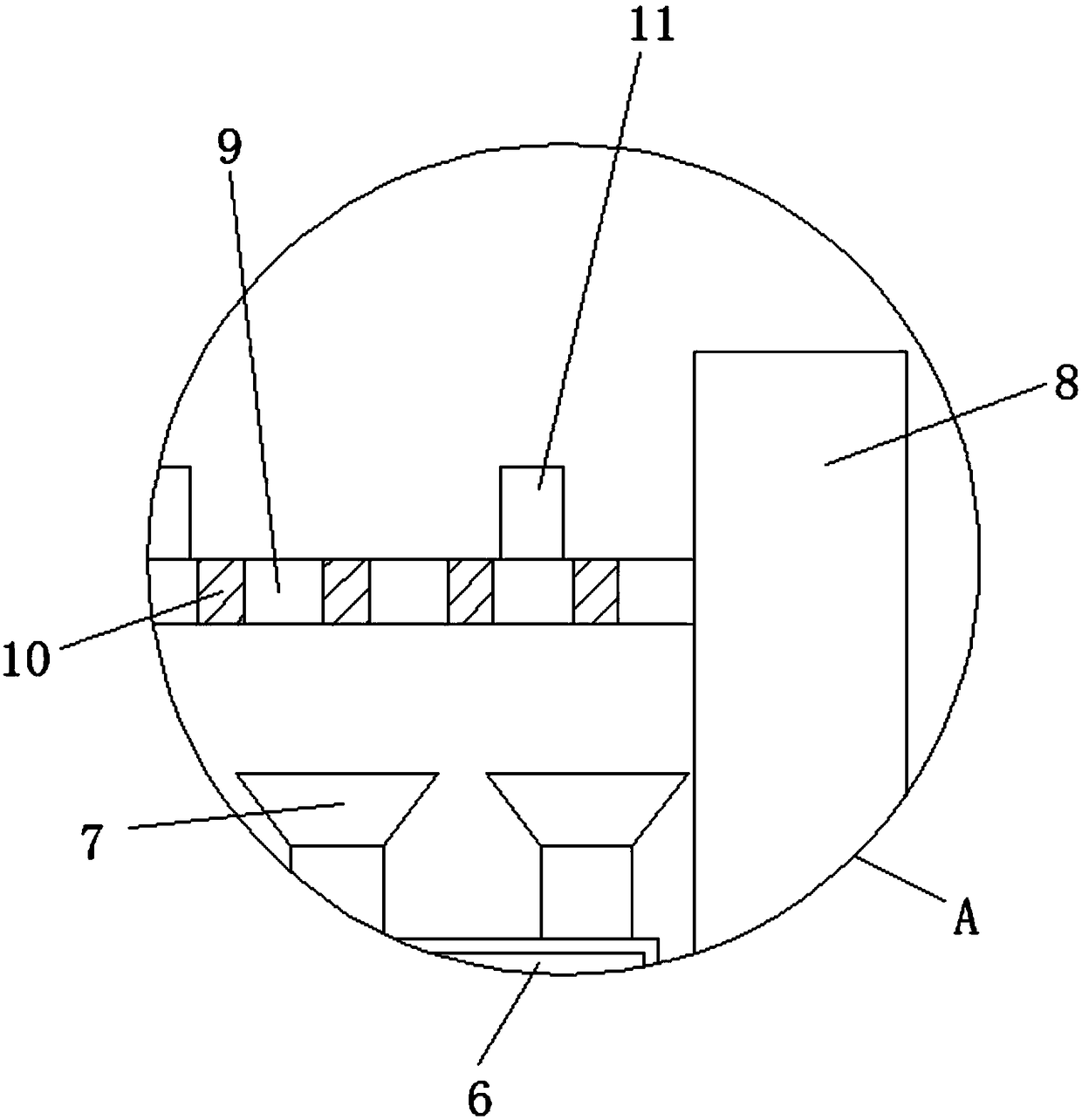

Image

  • Hot coating device for accelerating cooling
  • Hot coating device for accelerating cooling
  • Hot coating device for accelerating cooling

Examples


Embodiment Construction

[0019] The following will clearly and completely describe the technical solutions in the embodiments of the present invention with reference to the accompanying drawings in the embodiments of the present invention. Obviously, the described embodiments are only some, not all, embodiments of the present invention. Based on the embodiments of the present invention, all other embodiments obtained by persons of ordinary skill in the art without making creative efforts belong to the protection scope of the present invention.

[0020] see Figure 1-4 , the present invention provides a technical solution: a thermal coating device for accelerated cooling, such as figure 1 and figure 2 As shown, the upper side of the base 1 is provided with a shell 2, and the inside of the base 1 is provided with a groove 3, and the inside of the groove 3 is provided with a cooling fan 4, and there are four cooling fans 4, and the 4 cooling fans 4 are related to the base 1. The central axis of the ce...


PUM


Abstract

The invention discloses a hot coating device for accelerating cooling. The hot coating device for accelerating cooling comprises a base, a fixed plate, a workbin and an air extractor, wherein a shellis arranged on the upper side surface of the base; a groove is formed in the base; meanwhile, an air cooler is arranged in the groove; an air inlet pipe is arranged on the upper side surface of the air cooler and penetrates through the upper side surface of the base; an air inlet hollow plate is arranged on the upper side surface of the air inlet pipe; an air outlet is formed in the upper side surface of the air inlet hollow plate; the fixed plate is arranged on the upper side surface of the base and is arranged on the upper side of the air inlet hollow plate; meanwhile, the fixed plate is arranged on the inner side of the shell; a storage plate is arranged on the inner side surface of the fixed plate and is arranged on the upper side of the air outlet; and meanwhile, a through hole is formed in the upper surface of the storage plate. According to the hot coating device for accelerating cooling, the air outlet is formed, and after an object is sprayed, through the work of the air cooler, the air outlet blows air to dry the object on the upper side of the storage plate through the through hole, so that the working efficiency is improved.

Description

technical field [0001] The invention relates to the technical field of coating devices, in particular to a thermal coating device for accelerated cooling. Background technique [0002] The thermal coating device is a kind of material that sprays heat on some objects that need to be coated, so that the outer surface of the object can be protected. There are some problems in the current thermal coating device. When painting, the object is only placed on the storage plate with through holes, so that the coated side of the object is in contact with the storage plate to cause the material to be rubbed, and it needs to be sprayed again. The current thermal coating device is inside There is no mechanical cooling of the object, which reduces the work efficiency, and the current thermal spraying device does not take ventilation inside, which makes the internal smell of the spraying device particularly serious, and it is easy to cause a threat to the health of the workers. Therefore, ...

Claims


Application Information

Patent Timeline
Patent Type & Authority Applications(China)
IPC IPC(8): B05B16/20B05B13/02B05B13/04B05B14/40
CPCB05B16/20B05B13/0285B05B13/041B05B14/40
Inventor 周求湛
Owner 江苏纵湖涂装设备产业研究院有限公司
Learn More