Stepless shift baffle pin board

A technology of pin plate and displacement, which is applied in the field of construction equipment to achieve the effects of convenient processing, reduced frictional resistance, and less damage

Inactive Publication Date: 2019-03-08
冯广建
View PDF1 Cites 0 Cited by
  • Summary
  • Abstract
  • Description
  • Claims
  • Application Information

AI Technical Summary

Problems solved by technology

However, the structure of the above-mentioned adjustable anti-slip positioning mechanism can still be further improved to reduce the cost of manufacturing and processing

Method used


Image

  • Stepless shift baffle pin board
  • Stepless shift baffle pin board

Examples


Embodiment Construction

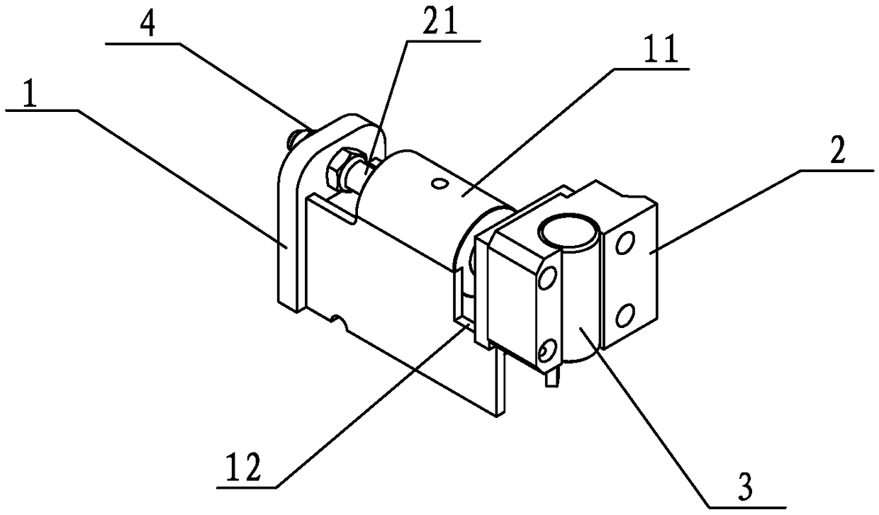
[0022] refer to figure 1 , the present invention provides a preferred embodiment of the stepless shift pin plate, including a positioning support 1, the positioning support 1 is provided with a shaft hole, the positioning support 1 is connected with a slide rail plate by welding, and the slide rail plate A flange bushing 11 is welded and fixed on the top, and a limit slide rail 12 is arranged in front of the slide rail plate. A stop pin plate 2 is slidably arranged on the limit slide rail 12, and a flange shaft 21 is arranged at the rear of the pin stop plate 2, and the flange shaft 21 passes through the flange bushing 11 and the shaft hole in turn, and is locked by the adjusting nut 4, The flange shaft 21 is provided with threads that match the adjusting nut 4, and the front and rear positions of the pin stop plate 2 can be easily adjusted by turning the adjusting nut 4. The front end of the pin stop plate 2 is provided with an arc-shaped groove, and the arc-shaped groove A ...


PUM


Abstract

The invention discloses a stepless shift baffle pin board. The stepless shift baffle pin board comprises a positioning support seat, a baffle pin board, a baffle pin and an adjusting nut, wherein a shaft hole is formed in the positioning support seat, a flanged shaft is arranged on the back part of the baffle pin board, the flanged shaft passes through the shaft hole, threads are formed on the flanged shaft, the adjusting nut is installed on the flanged shaft and is matched with the positioning support seat so as to fix the baffle pin board, and the baffle pin is rotatably arranged on the front end of the baffle pin board. The flanged shaft passes through the shaft hole of the positioning support seat and is fixed by adopting the adjusting nut, and the front-and-back position of the bafflepin board can be conveniently adjusted by rotating the adjusting nut, so that stepless shift adjustment is realized, and different specifications of steel bars can be bent; the threaded connection and fixing are adopted, so that slip shifting cannot be generated; and the baffle pin on the baffle pin board is rotatably arranged, so that the frictional resistance with the steel bars can be reducedby virtue of rotation when the steel bars are bent, and the surfaces of the steel bars are prevented from being damaged. The stepless shift baffle pin board has the great advantages of convenience instructure machining, low cost and easiness in adjustment.

Description

technical field [0001] The invention relates to the field of construction equipment, in particular to a stepless shift pin plate used for a steel bar bending machine. Background technique [0002] An existing steel bar bending forming machine uses a turntable, a central pin shaft and a rotating pin shaft to cooperate to bend steel bars, wherein the turntable is driven by a power device to rotate, and the rotating pin shaft is fixed on the turntable to rotate with the turntable, and the turntable and the rotating pin The shaft rotates around the center pin shaft, and the steel bar placed between the rotation pin shaft and the center pin shaft is bent by using the moment generated by the rotation of the rotating pin shaft. [0003] In order to fix the steel bar so that it will not swing freely when bending, a positioning structure needs to be arranged next to the turntable, and the positioning structure cooperates with the central pin shaft to fix the steel bar. The positioni...

Claims


Application Information

Patent Timeline
Patent Type & Authority Applications(China)
IPC IPC(8): B21F1/00
CPCB21F1/004
Inventor 冯广建
Owner 冯广建
Why Eureka
Try Eureka