Automatic metal pipe cutting device

A technology for cutting devices and metal pipes, which is applied in the direction of pipe shearing devices, shearing devices, and accessories of shearing machines, etc. It can solve the problems that the angle grinder is difficult to cut out the incision, and the pipe cutter cannot cope with pipe wall pipes, etc., and achieves The effect of precise movement distance

Pending Publication Date: 2019-03-08
江苏众利达自动化设备有限公司
View PDF0 Cites 5 Cited by
  • Summary
  • Abstract
  • Description
  • Claims
  • Application Information

AI Technical Summary

Problems solved by technology

[0003] Metal pipes often need to be cut at a longer length in daily use. Pipe cutters cannot cope with pipes with thicker walls. It is difficult for angle grinders to cut a relatively flat incision. Nozzle

Method used


Image

  • Automatic metal pipe cutting device
  • Automatic metal pipe cutting device

Examples


Embodiment Construction

[0015] The following will clearly and completely describe the technical solutions in the embodiments of the present invention with reference to the accompanying drawings in the embodiments of the present invention. Obviously, the described embodiments are only some, not all, embodiments of the present invention. Based on the embodiments of the present invention, all other embodiments obtained by persons of ordinary skill in the art without making creative efforts belong to the protection scope of the present invention.

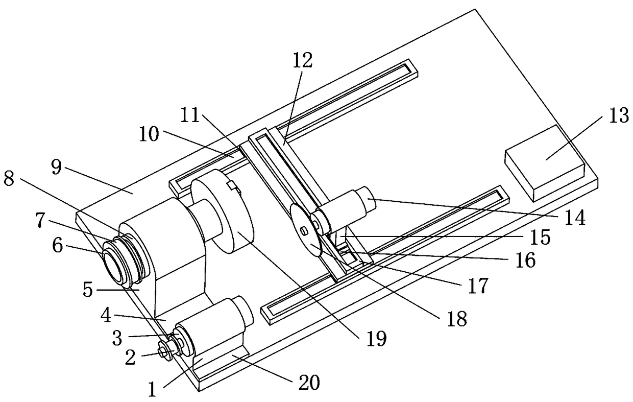
[0016] The present invention provides such Figure 1-2 A metal tube automatic cutting device shown includes a mounting plate 9, a rotating tube 6, a fixed motor 3, a three-jaw chuck 19, a movable motor 14, a first electric guide rail 10 and a second electric guide rail 17, the installation The outer contour of the supporting plate 9 is a rectangular plate-shaped structure, and the upper surface of the mounting plate 9 is provided with a fixed motor base 1 near...


PUM


Abstract

The invention discloses an automatic metal pipe cutting device which comprises an installation support plate, a rotary pipe, a fixed motor, a three-jaw chuck, a movable motor, a first electric guide rail and a second electric guide rail. The outer contour of the installation support plate is of a rectangular platy structure; a fixed motor base is arranged at the position, close to the edge, of oneside on the upper surface of the installation support plate; a motor bottom plate with a platy-structure contour is arranged on the bottom part of the fixed motor base; the fixed motor is arranged inthe upper end of the fixed motor base; a motor belt pulley sleeves an output shaft of the fixed motor; a ball bearing is arranged in the top end of an installation stand column on the installation support plate; the rotary pipe is arranged in the ball bearing; a pipeline belt pulley fixedly sleeves the position, on the same side of the output shaft of the fixed motor, of the rotary pipe; and thethree-jaw chuck is arranged at one end, far away from the pipeline belt pulley, of the rotary pipe. The automatic metal pipe cutting device has the advantage of smoothness in notches and convenience in adjusting the size, and is suitable for widely popularizing and using.

Description

technical field [0001] The invention belongs to the technical field of metal pipe cutting devices, in particular to an automatic metal pipe cutting device. Background technique [0002] A metal tube with a hollow section whose length is much greater than the diameter or circumference of steel. According to the cross-sectional shape, it is divided into circular, square, rectangular and special-shaped metal pipes; according to its use, it is divided into metal pipes for transportation pipelines, engineering structures, thermal equipment, petrochemical industry, machinery manufacturing, geological drilling, and high-pressure equipment. According to the production process, it is divided into seamless metal pipe and welded metal pipe, among which seamless metal pipe is divided into hot rolling and cold rolling, and welded metal pipe is divided into straight seam welded metal pipe and spiral seam welded metal pipe. [0003] Metal pipes often need to be cut at a longer length in d...

Claims


Application Information

Patent Timeline
Patent Type & Authority Applications(China)
IPC IPC(8): B23D21/00B23D33/02
CPCB23D21/00B23D33/02
Inventor 邵先雨武月超晁岱卫晁岱庆
Owner 江苏众利达自动化设备有限公司
Why Eureka
Try Eureka