Powder pressing machine

A pressing machine and powder technology, which is applied in the direction of punching machine, press, material forming press, etc., can solve the problems that the product does not meet the density and the punching strength does not meet the requirements, so as to improve the density and pressing density high effect

Pending Publication Date: 2019-03-08
东莞市新日宝成形机器设备有限公司
View PDF11 Cites 2 Cited by
  • Summary
  • Abstract
  • Description
  • Claims
  • Application Information

AI Technical Summary

Problems solved by technology

[0002] Stamping is to rely on stamping device and mold to apply external force to powder, plate, strip, pipe and profile, etc., so that it can be plastically deformed or separated, so as to obtain a workpiece of required shape and size. In powder compaction processing , powder compactor is a kind of commonly used processing equipment, it is the equipment that utilizes external pressure to press powder forming in the mold device, the existing powder compactor compacting forming process is mainly composed of powder loading, compacting and demolding, usually powder compacting The machine includes a frame, an upper punching device, a lower punching device and a mold device. The mold device is provided with one or more mold cavities, and the powder material can be filled into the mold cavity, and pressed by the upper punching device and the lower punching device to form a pressed product. Now Some powder compactors mostly adopt the servo stamping method, but for products with high density requirements, the stamping strength of the above structure often fails to meet the requirements, resulting in the pressed products not reaching the required density

Method used


Image

  • Powder pressing machine
  • Powder pressing machine
  • Powder pressing machine

Examples


Embodiment Construction

[0022] The present invention will be further described below in conjunction with the accompanying drawings.

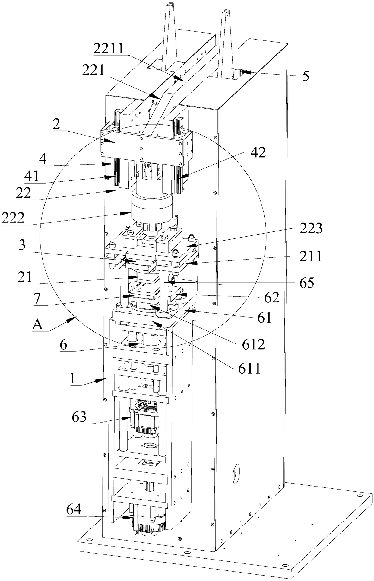
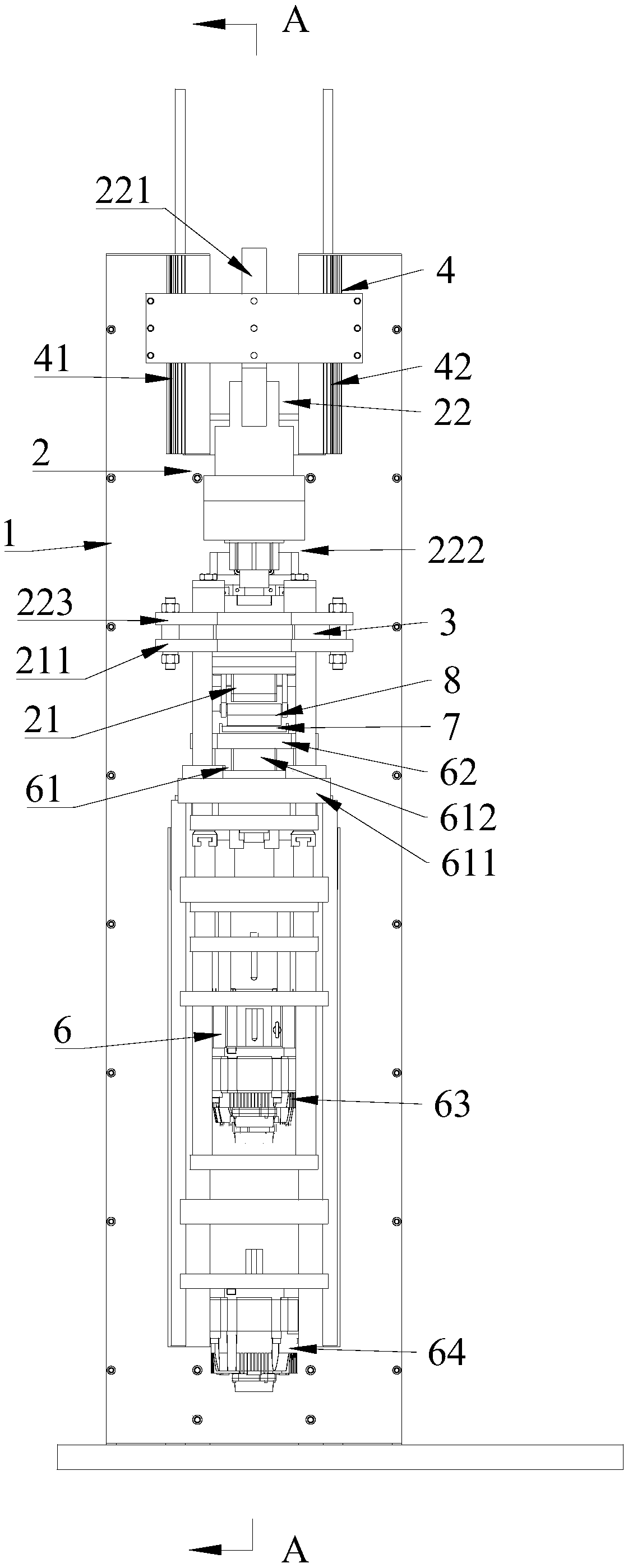
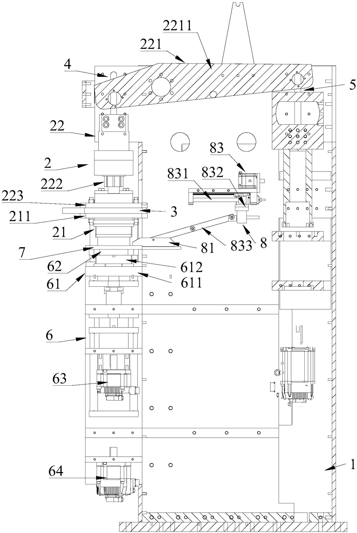
[0023] refer to Figure 1 to Figure 4 , a kind of powder pressing machine, comprises frame 1, upper punching device 2, lower punching device 6 and die device 7, upper punching device 2 and lower punching device 6 are respectively positioned at the upper and lower sides of die device 7, and lower punching device 6 includes The lower punch assembly 61 provided on the frame 1, the connection seat 62 connected with the mold device 7, and the first drive mechanism 63 connected with the connection seat 62 in transmission, the mold device 7 can be relatively upward under the action of the first drive mechanism 63 The punch assembly 21 moves up and down, and the upper punching device 2 is provided with an upper punch assembly 21, a second driving mechanism 22 and a coil assembly 3, and the coil assembly 3 is installed between the upper punch assembly 21 and the second driving ...


PUM


Abstract

The invention relates to a powder pressing machine. The powder pressing machine comprises a rack, an upper punching device, a lower punching device and a die device, wherein the upper punching deviceand the lower punching device are respectively located on the upper and lower sides of the die device, the lower punching device comprises a lower punch assembly which is installed on the rack, a connecting seat which is connected with the die device and a first driving mechanism which is in driving connection with the connecting seat, the die device can move up and down relative to an upper punchassembly under the action of the first driving mechanism, the upper punching device is provided with the upper punch assembly, a second driving mechanism and a coil assembly, the coil assembly is installed between the upper punch assembly and the second driving mechanism, and an electric box is electrically connected to the coil assembly. Compared with the prior art, the powder pressing machine is combined with a servo punching mode and a pulse punching mode so as to punch a pressing piece for two times, so that the density of finished products is greatly increased.

Description

technical field [0001] The invention relates to the technical field of molding machines, in particular to a powder compacting machine. Background technique [0002] Stamping is to rely on stamping device and mold to apply external force to powder, plate, strip, pipe and profile, etc., so that it can be plastically deformed or separated, so as to obtain a workpiece of required shape and size. In powder compaction processing , powder compactor is a kind of commonly used processing equipment, it is the equipment that utilizes external pressure to press powder forming in the mold device, the existing powder compactor compacting forming process is mainly composed of powder loading, compacting and demolding, usually powder compacting The machine includes a frame, an upper punching device, a lower punching device and a mold device. The mold device is provided with one or more mold cavities, and the powder material can be filled into the mold cavity, and pressed by the upper punchin...

Claims


Application Information

Patent Timeline
Patent Type & Authority Applications(China)
IPC IPC(8): B30B1/42B30B11/04B30B11/06B30B15/06B30B15/30B30B15/32
CPCB30B1/42B30B11/027B30B11/04B30B11/06B30B15/065B30B15/302B30B15/32
Inventor 饶俊华尧巍华
Owner 东莞市新日宝成形机器设备有限公司
Why Eureka
Try Eureka