Tool hoisting device used for shield tunneling machine

A technology of shield machine tool and hoisting device, which is applied to cranes and other directions, can solve the problems of high processing cost, troublesome tool replacement, and high use environment requirements, and achieve the effects of high efficiency and stability, improved efficiency, and simple and reliable structure.

Active Publication Date: 2019-03-08
XIAMEN XIAGONG CHINA RAILWAY HEAVY MACHINERY CO LTD
View PDF9 Cites 2 Cited by
  • Summary
  • Abstract
  • Description
  • Claims
  • Application Information

AI Technical Summary

Problems solved by technology

However, it is very troublesome to replace the cutting tool at present, the labor intensity of the workers is high, and the replacement efficiency is low
[0003] The announcement number is CN 204702458 U disclosed a kind of shield machine tool hoisting structure, such as figure 1 As shown, including the base plate 1', the base plate 1' is provided with a hoisting seat 2', the hoisting seat 2' is provided with a driving motor 3', and the driving motor 3' is driven and connected with a ball screw seat 4', the ball screw A ball screw 5' is arranged inside the seat 4', a moving block 6' is connected to the ball screw 5', a lifting rod 7' is connected to the moving block 6', and a lifting hook 8' is slidingly connected to the lifting rod 7', Because the cutting tool needs to be hoisted into the man cabin of the shield machine, and the installation position of the man cabin is generally installed on the top of the shield machine, and the height difference is large, the disadvantages caused by the above scheme: 1. A single knife of the shield machine is generally more than 150kg, and the ball The 5' lead screw is easy to bend and deform under the condition of long-distance load; 2. The structure and installation accuracy of the ball screw 5' are high, the processing cost is high, and the requirements for the use environment are high; 3. The ball screw 5' is used for transmission, Requires complex power system and supporting structures and devices

Method used


Image

  • Tool hoisting device used for shield tunneling machine
  • Tool hoisting device used for shield tunneling machine
  • Tool hoisting device used for shield tunneling machine

Examples


Embodiment Construction

[0021] The present invention will be described in detail below in conjunction with the accompanying drawings and specific embodiments.

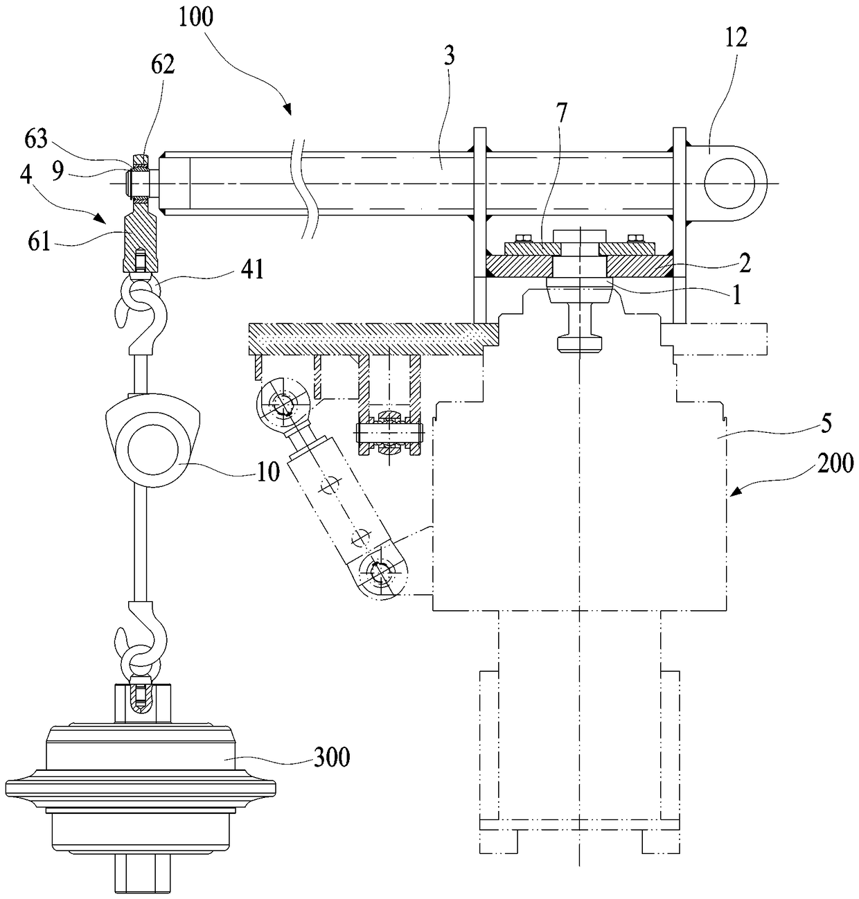
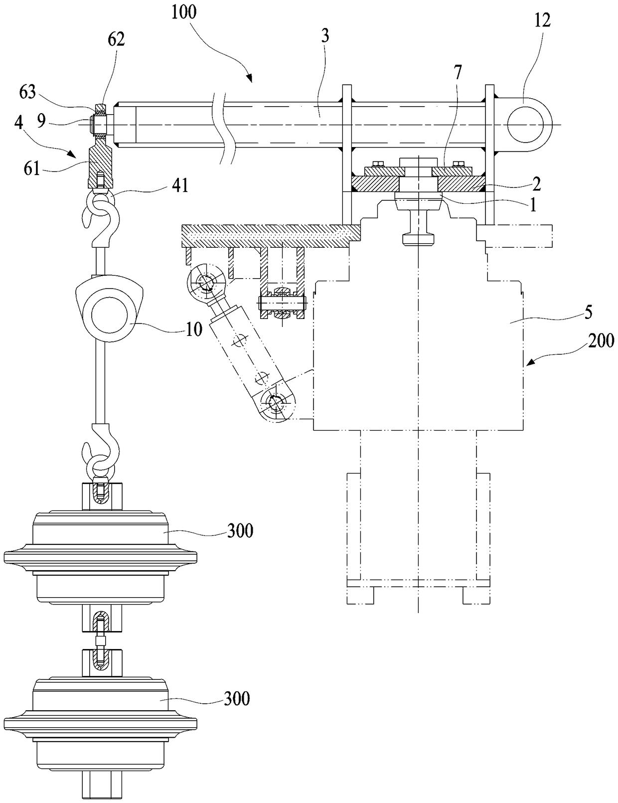
[0022] Such as Figure 2 to Figure 6 As shown, a shield machine tool lifting device disclosed in the present invention includes a lifting device 100. The lifting device 100 includes a lifting shaft 1, a connecting plate 2, a rod body 3 and a hook 4. One end of the lifting shaft 1 is used for snatching with the assembly machine. The head 5 is tightly connected, the other end is fixed on the bottom of the connecting plate 2, one end of the rod body 3 is fixedly connected to the side connected to the connecting plate 2, and the other end is connected to the hook 4, and the hook 4 can rotate around the radial end of the rod body 3 . The way that the lifting shaft 1 is tightly connected to the lifting head 5 of the assembly machine is preferably to act on the lifting shaft 1 through the assembly lifting button provided in the lifting head 5 of th...


PUM


Abstract

The invention discloses a tool hoisting device used for a shield tunneling machine. The tool hosting device comprises a hoisting device body. The hoisting device body comprises a hoisting shaft, a connecting plate, a rod body and a lifting hook. One end of the hosting shaft is fixedly connected with a grabbing head of a splicing device, and the other end of the hoisting shaft is fixed to the bottom of the connecting plate. One end of the rod body is fixedly connected to the side face of the connecting plate, and the other end of the rod body is connected with the lifting hook. The lifting hookcan rotate around the radial end of the rod body. When the grabbing head of the splicing device is fixedly connected with the hoisting shaft, a segment splicing and lifting device rotates and rises or falls to drive the hosing device body to change in altitude, and thus, a tool hung on the lifting hook is transferred towards a cabin of the tool hoisting device. By adoption of the design, the toolhoisting device is simple and reliable in structure, the hoisting shaft is grabbed through the grabbing head of the splicing machine on the shield tunneling machine, and then, the whole tool hoistingdevice is driven to move.

Description

technical field [0001] The invention relates to a shield mechanism, in particular to a tool hoisting device for a shield machine. Background technique [0002] The knives on the shield machine are wearing parts. After a period of use, the knives will be severely worn. At this time, the knives need to be replaced so that the shield machine can maintain a good working condition. However, it is very troublesome to replace the cutter at present, the labor intensity of the workers is high, and the replacement efficiency is low. [0003] The announcement number is CN 204702458 U disclosed a kind of shield machine tool hoisting structure, such as figure 1 As shown, including the base plate 1', the base plate 1' is provided with a hoisting seat 2', the hoisting seat 2' is provided with a driving motor 3', and the driving motor 3' is driven and connected with a ball screw seat 4', the ball screw A ball screw 5' is arranged inside the seat 4', a moving block 6' is connected to the b...

Claims


Application Information

Patent Timeline
Patent Type & Authority Applications(China)
IPC IPC(8): B66C23/36B66C23/62B66C23/69
CPCB66C23/36B66C23/62B66C23/701
Inventor 郑伟陈贝贝郭宏耀刘恒吕专真李峰陈福涛
Owner XIAMEN XIAGONG CHINA RAILWAY HEAVY MACHINERY CO LTD
Why Eureka
Try Eureka