Photoelectric conversion device and communication system

A photoelectric conversion device and electro-optical conversion technology, applied in the field of communication, can solve problems such as poor stability, poor transmission signal security, and influence on overall line communication, and achieve the effect of small size, low power consumption, safe and stable transmission

Inactive Publication Date: 2019-03-08
ARMY ENG UNIV OF PLA
View PDF16 Cites 1 Cited by
  • Summary
  • Abstract
  • Description
  • Claims
  • Application Information

AI Technical Summary

Problems solved by technology

[0004] In view of this, the present invention provides a photoelectric conversion device and a communication system, aiming at the problems in the prior art that when the photoelectric conversion device fails, it affects the communication of the whole line, the stability is poor, and the security of the transmission signal is poor

Method used


Image

  • Photoelectric conversion device and communication system
  • Photoelectric conversion device and communication system
  • Photoelectric conversion device and communication system

Examples


Embodiment 1

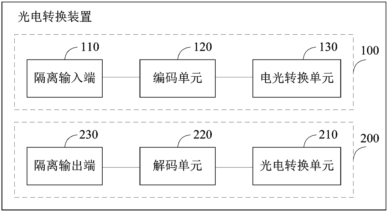
[0057] see figure 1 , a photoelectric conversion device provided by an embodiment of the present invention includes: a signal transmitting module 100 and a signal receiving module 200; the signal transmitting module 100 and the signal receiving module 200 are connected in parallel.

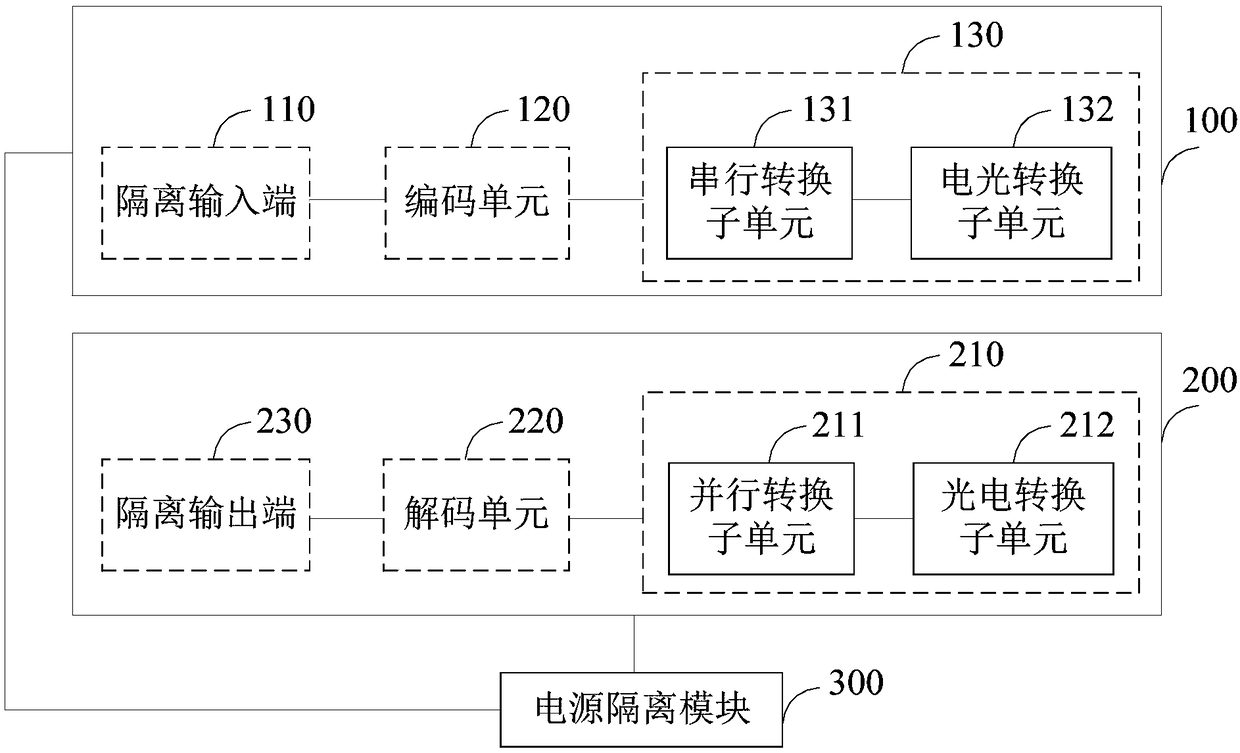
[0058] Wherein, the signal transmitting module 100 includes: an isolation input terminal 110, an encoding unit 120 and an electro-optical conversion unit 130; the isolation input terminal 110, the encoding unit 120 and the electro-optic conversion unit 130 are connected in sequence.

[0059] The encoding unit 120 is used to encode the optical fiber data received by the isolated input terminal 110 to obtain encoded data, and send the encoded data to the electro-optical conversion unit 130; the electro-optical conversion unit 130 is used to convert the encoded data into optical fiber data signals emission.

[0060] The signal receiving module 200 includes: a photoelectric conversion unit 210 , a de...

Embodiment 2

[0103] Based on the photoelectric conversion device provided in Embodiment 1 above, this embodiment provides a communication system. The communication system includes an optical-electrical hybrid cable, and is characterized in that it further includes any one of the photoelectric conversion devices provided in the first embodiment above, which is connected to the optical-electrical hybrid cable, and also has the beneficial effects of the first embodiment above.

[0104] Specifically, see Figure 9 , the photoelectric conversion device can be used not only as a receiving module, but also as a transmitting module, and the photoelectric conversion device is connected with a photoelectric hybrid cable to realize optical fiber communication. The communication system of this embodiment does not limit the number of photoelectric conversion devices, and may be multiple or two.

[0105] Exemplary, see Figure 10 , the communication system of this embodiment can also be used as an aux...


PUM


Abstract

The invention belongs to the technical field of communication, and provides a photoelectric conversion device and a communication system. The device comprises: a signal transmitting module and a signal receiving module; wherein the signal transmitting module comprises: an isolated input end, an encoding unit and an electro-optic conversion unit, the encoding unit encodes optical fiber data received by the isolated input end to obtain encoded data and sends the encoded data to the electro-optic conversion unit, and the electro-optic conversion unit converts the encoded data into an optical fiber data signal for transmission; and the signal receiving module comprises: a photoelectric conversion unit, a decoding unit and an isolated output end, the photoelectric conversion unit converts received optical fiber transmission data into a parallel signal and sends the parallel signal to the decoding unit, and the decoding unit decodes the parallel signal to obtain transmission data and outputsthe transmission data to an external photoelectric hybrid cable through the output end. The photoelectric conversion device provided by the invention has low power consumption and a small size, and realizes safe and fast transmission of signals, and meanwhile, the signal transmitting module and the signal receiving module can be used as transmission links and have a dual optical fiber backup function.

Description

technical field [0001] The invention belongs to the technical field of communication, and more specifically relates to a photoelectric conversion device and a communication system. Background technique [0002] When the anti-aircraft missile weapon system performs tasks, cable connections should be made between different equipment according to the task requirements. For example, in the missile test, the cables need to be connected between the missile test vehicle and the missile test control vehicle, and the number of connected cables is large. , heavy weight, which affects the speed of deployment and withdrawal of equipment, and increases the difficulty and intensity of the operator's work. In order to deal with the above problems, an optical-electrical hybrid signal transmission technology has been adopted in the prior art to solve it. Optical fiber communication is an emerging wired communication technology that uses light waves as the carrier and optical fiber as the in...

Claims


Application Information

Patent Timeline
Patent Type & Authority Applications(China)
IPC IPC(8): H04B10/40H04B10/50
CPCH04B10/40H04B10/503
Inventor 姜会霞魏保华范书义杨锁昌赵慎
Owner ARMY ENG UNIV OF PLA
Why Eureka
Try Eureka