Supercharge Your Innovation With Domain-Expert AI Agents!

Zoom lens structure suitable for high-magnification lens

A zoom lens, high magnification technology, used in installation, optics, instruments, etc., can solve the problems of difficult to find the lens out of step and idling, the motor structure has become a chicken rib, redundant focus step table, etc., to improve the service life and durability. Sensitive, fast and precise adjustment of the effect of the control

Pending Publication Date:
View PDF5 Cites 0 Cited by
  • Summary
  • Abstract
  • Description
  • Claims
  • Application Information

AI Technical Summary

Problems solved by technology

In order to meet the needs of the market, more and more lenses need to use high-resolution large chips, and zoom lenses must also be used in different fields and environments, resulting in a corresponding increase in lens magnification and more and more. , the current zoom lens is a focus group, a zoom group, each with a motor, usually a zoom motor, the test data is a very lengthy table of focus steps, and the convenience will become more and more Difficult to find problems such as out-of-step and backlash of the lens. In the current situation where the magnification requirements are increasing, if the lens needs to achieve a large magnification, the travel distance of the zoom group must be greater and the stroke longer. The longer it has to be, and the shape of the lens cannot be enlarged infinitely, and even many application places have space restrictions. In addition, when there is a problem with the zoom group, all parts of the zoom group need to be disassembled for inspection. , it is very troublesome to disassemble and assemble, so the longer and longer motor structure will gradually become tasteless

Method used


Image

  • Zoom lens structure suitable for high-magnification lens
  • Zoom lens structure suitable for high-magnification lens
  • Zoom lens structure suitable for high-magnification lens

Examples


Embodiment Construction

[0019] The present invention will be further described below in conjunction with accompanying drawing:

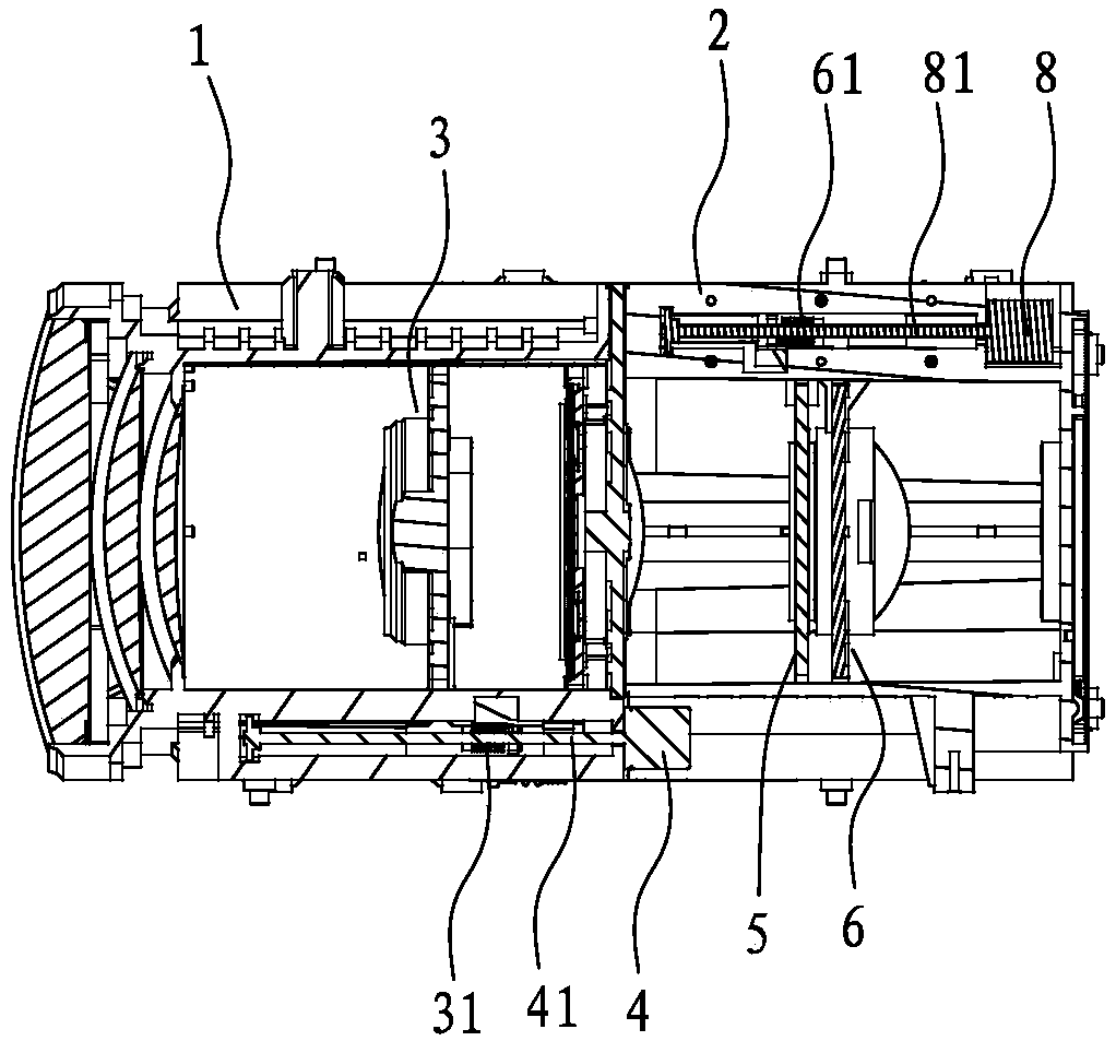
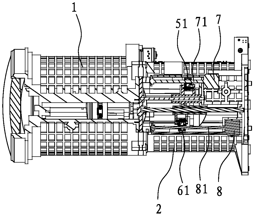
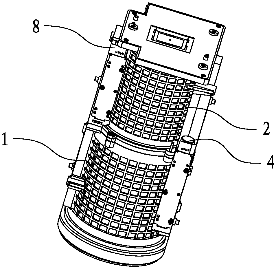
[0020] Such as Figure 1 to Figure 4 A zoom lens structure suitable for high-magnification lenses is shown, including a front lens barrel 1 and a rear lens barrel 2, and the front lens barrel 1 is provided with a focus lens group 3 that can slide therein, and the focus lens The group 3 is fixed with a first nut 31, the front lens barrel 1 is provided with a focus motor 4, and the focus motor 4 is fixed with a first screw 41 threadedly connected with the first nut 31, and the rear lens barrel 2 The first zoom lens group 5 and the second zoom lens group 6, which are independent of each other, are slidably connected in the front and rear directions, and the first zoom lens group 5 and the second zoom lens group 6 are respectively fixed with a second nut 51 and a third nut. nut 61, the rear lens barrel 2 is provided with a first zoom motor 7 and a second zoom motor 8, the firs...


PUM


Abstract

The invention discloses a zoom lens structure suitable for a high-magnification lens. The zoom lens structure comprises a front lens cone and a rear lens cone, a focusing lens group which can slide inthe front lens cone is arranged in the front lens cone, and a first nut is fixed to the focusing lens group; a focusing motor is arranged on the front lens cone, a first screw in threaded connectionwith the first nut is fixed to the focusing motor, and a first zoom lens group and a second zoom lens group which are independent of each other are slidingly connected in the rear lens cone in the front-rear direction; a second nut and a third nut are fixed to the first zoom lens group and the second zoom lens group respectively, a first zoom lens motor and a second zoom lens motor are arranged onthe rear lens cone, a second screw in threaded connection with the second nut is fixed to the first zoom lens motor, and a third screw in threaded connection with the third nut is fixed to the secondzoom lens motor. The structure is simple, the lens is decomposed into the lens groups, stroke control is conducted through the motors, the stoke displacement is reduced, and the appearance size of the optical lens is reduced.

Description

【Technical field】 [0001] The invention relates to a zoom lens structure suitable for high magnification lenses. 【Background technique】 [0002] With the rapid development of high technology, security optical zoom lens has been widely used. In order to meet the needs of the market, more and more lenses need to use high-resolution large chips, and zoom lenses must also be used in different fields and environments, resulting in a corresponding increase in lens magnification and more and more. , the current zoom lens is a focus group, a zoom group, each with a motor, usually a zoom motor, the test data is a very lengthy table of focus steps, and the convenience will become more and more Difficult to find problems such as out-of-step and backlash of the lens. In the current situation where the magnification requirements are increasing, if the lens needs to achieve a large magnification, the travel distance of the zoom group must be greater and the stroke longer. The longer it h...

Claims


Application Information

Patent Timeline
Patent Type & Authority Applications(China)
IPC IPC(8): G02B7/04G02B7/09
CPCG02B7/04G02B7/09
Inventor 王琦邱盛平李中杰李昆陈新吴恙
Features
  • R&D
  • Intellectual Property
  • Life Sciences
  • Materials
  • Tech Scout
  • Unparalleled Data Quality
  • Higher Quality Content
  • 60% Fewer Hallucinations
Learn More