Throttling element, differential pressure type pulmonary function parameter monitoring device and flow rate confirming method

A technology of pulmonary function parameters and monitoring devices, applied in diagnostic recording/measurement, medical science, diagnostic signal processing, etc., can solve the problems of being easily affected by the moment of inertia, easily affected by the environment, and greatly affected by eddy currents, etc., to achieve Length requirements are reduced, measurement accuracy is improved, and the effect of airflow is achieved

Active Publication Date: 2018-09-28
INST OF ELECTRONICS CHINESE ACAD OF SCI
View PDF5 Cites 8 Cited by
  • Summary
  • Abstract
  • Description
  • Claims
  • Application Information

AI Technical Summary

Problems solved by technology

Among them, the differential pressure type calculates the flow rate according to the differential pressure generated by the airflow passing through the throttling part, which has the advantages of simple structure, low cost, and good repeatability, but there are also zero drift, large pressure loss, narrow range, and great influence by eddy currents. Disadvantages; the hot-wire scheme is based on the principle of heat transfer, and the current of the sensor is proportional to the flow rate. It has high sensitivity and good accuracy, but it is easily affected by the environment, expensive and easy to damage; the turbine scheme is based on the turbine The rotation speed is proportional to the flow rate, and the measurement range is wide, but it is easily affected by the moment of inertia

Method used

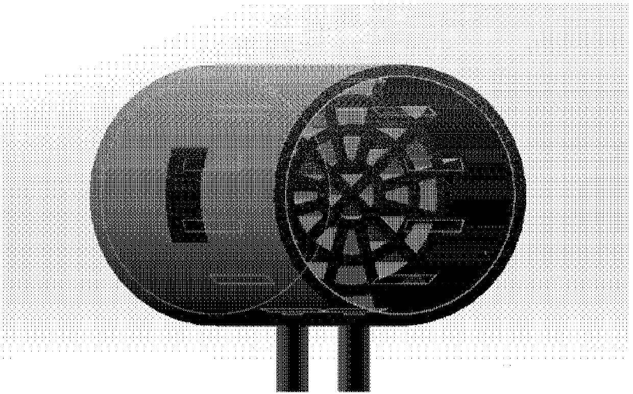
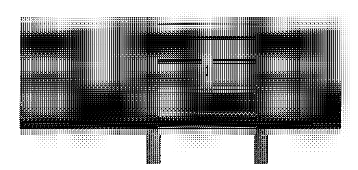
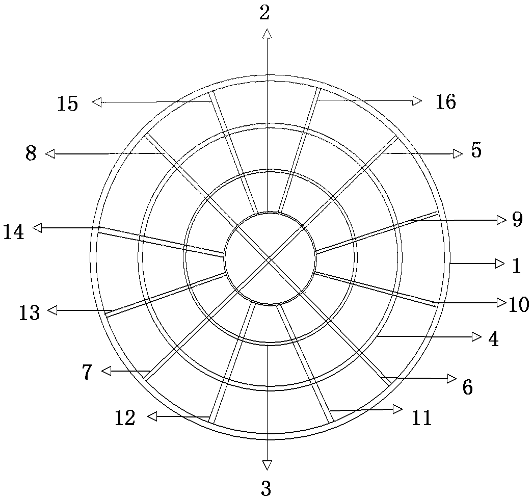

Image

  • Throttling element, differential pressure type pulmonary function parameter monitoring device and flow rate confirming method
  • Throttling element, differential pressure type pulmonary function parameter monitoring device and flow rate confirming method
  • Throttling element, differential pressure type pulmonary function parameter monitoring device and flow rate confirming method

Examples


Embodiment Construction

[0035] In order to make the purpose, technical solutions and advantages of the present disclosure clearer, the present disclosure will be further described in detail below in conjunction with specific embodiments and with reference to the accompanying drawings.

[0036] It should be noted that, in the drawings or descriptions of the specification, similar or identical parts all use the same figure numbers. Implementations not shown or described in the accompanying drawings are forms known to those of ordinary skill in the art. Additionally, while illustrations of parameters including particular values ​​may be provided herein, it should be understood that the parameters need not be exactly equal to the corresponding values, but rather may approximate the corresponding values ​​within acceptable error margins or design constraints. The directional terms mentioned in the embodiments, such as "upper", "lower", "front", "rear", "left", "right", etc., are only referring to the dire...


PUM


Abstract

The invention provides a throttling element, a differential pressure type pulmonary function parameter monitoring device and a flow rate confirming method. The porous throttling element comprises a pipe and a throttling porous plate, wherein an airflow channel is formed via the pipe; the throttling porous plate is arranged in the pipe, and the throttling porous plate comprises a plurality of firstcomponents and a plurality of second components; the plurality of first components are distributed in a mode of being coaxial with the pipe; the plurality of second components are distributed in thepipe in a radial form; therefor, a plurality of tubular throttling holes are formed in the airflow channel via the plurality of first components and the plurality of second components. The throttlingelement, the differential pressure type pulmonary function parameter monitoring device and the flow rate confirming method provided by the invention are simple in structure and low in cost; a requirement on the length of a straight-pipe section is reduced and a measuring range is widened; vortex, which appears under a high-flow-rate condition in an expiration / inspiration process, is effectively improved; airflow balance is realized; and repeatability and reliability are improved.

Description

technical field [0001] The present disclosure relates to the technical field of portable medical equipment, in particular, to a throttling member, a differential pressure pulmonary function parameter monitoring device and a flow determination method. Background technique [0002] Currently, there are three commonly used sensor types for measuring pulmonary function parameters: differential pressure, hot wire, and turbine. Among them, the differential pressure type calculates the flow rate according to the differential pressure generated by the airflow passing through the throttling part, which has the advantages of simple structure, low cost, and good repeatability, but there are also zero drift, large pressure loss, narrow range, and great influence by eddy currents. Disadvantages; the hot-wire scheme is based on the principle of heat transfer, and the current of the sensor is proportional to the flow rate. It has high sensitivity and good accuracy, but it is easily affecte...

Claims


Application Information

Patent Timeline
Patent Type & Authority Applications(China)
IPC IPC(8): A61B5/087A61B5/00
CPCA61B5/087A61B5/0871A61B5/72A61B5/7203A61B5/7235
Inventor 方震贾天震周旺赵荣建陈贤祥赵湛杜利东
Owner INST OF ELECTRONICS CHINESE ACAD OF SCI
Why Eureka
Try Eureka