A polymer plastic-steel type ladder bridge

A polymer, plastic steel technology, applied in the direction of electrical components, etc., can solve the problem that the ladder bridge can not be stretched, can not adjust the reserved length of the cable end, etc., to achieve the effect of simple structure and easy adjustment

Active Publication Date: 2020-06-05
ANHUI TIANCAI CABLE GRP
View PDF4 Cites 0 Cited by
  • Summary
  • Abstract
  • Description
  • Claims
  • Application Information

AI Technical Summary

Problems solved by technology

[0004] What the present invention aims to overcome is the problem that the ladder bridge cannot be stretched or adjusted, and the reserved length of the cable end cannot be adjusted. The purpose is to provide a polymer plastic-steel ladder bridge

Method used


Image

  • A polymer plastic-steel type ladder bridge
  • A polymer plastic-steel type ladder bridge
  • A polymer plastic-steel type ladder bridge

Examples


Embodiment 1

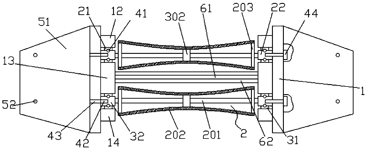
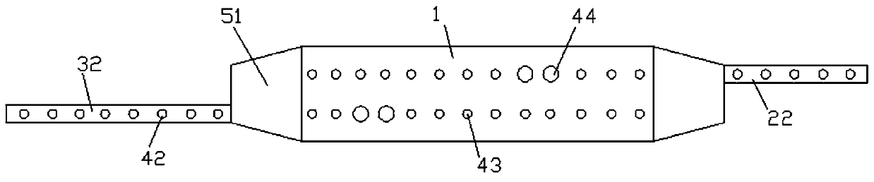
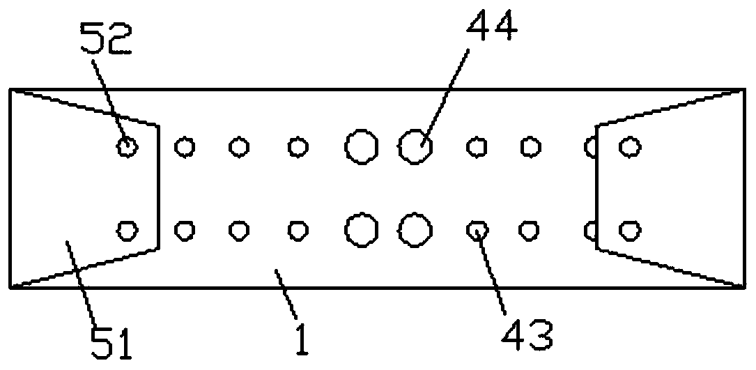
[0021] Such as figure 1 Shown; a polymer plastic-steel type ladder bridge, including two sets of ladder sides 1, and the ladder beam 2 installed in parallel between the two sets of ladder sides 1, the inner sides of the two sets of ladder sides 1 are installed with the first fixed steel 12. The second fixed steel 13, the third fixed steel 14, the adjacent surfaces between the first fixed steel 12 and the second fixed steel 13 are respectively equipped with first slide rails 21, and the two sets of first slide rails 21 are installed with First slide bar 22, ladder beam 2 is installed on the first slide bar 22 on two groups of ladder sides 1, the second slide rail 31 is installed on the adjacent surface of second fixed steel 13 and the 3rd fixed steel 14 respectively, two The second slide bar 32 is installed between the second slide rails 31 of the group, the ladder beam 2 is installed on the second slide bar 32 on the two sets of ladder sides 1, the first slide bar 22 and the t...

Embodiment 2

[0028] Such as figure 1 Shown; a polymer plastic-steel type ladder bridge, including two sets of ladder sides 1, and the ladder beam 2 installed in parallel between the two sets of ladder sides 1, the inner sides of the two sets of ladder sides 1 are installed with the first fixed steel 12. The second fixed steel 13, the third fixed steel 14, the adjacent surfaces between the first fixed steel 12 and the second fixed steel 13 are respectively equipped with first slide rails 21, and the two sets of first slide rails 21 are installed with First slide bar 22, ladder beam 2 is installed on the first slide bar 22 on two groups of ladder sides 1, the second slide rail 31 is installed on the adjacent surface of second fixed steel 13 and the 3rd fixed steel 14 respectively, two The second slide bar 32 is installed between the second slide rails 31 of the group, the ladder beam 2 is installed on the second slide bar 32 on the two sets of ladder sides 1, the first slide bar 22 and the t...


PUM


Abstract

The invention discloses a macromolecule PVC profile ladder type bridge. The macromolecule PVC profile ladder type bridge comprises two groups of ladder sides and ladder beams arranged between two groups of ladder sides in parallel; a first fixed steel, a second fixed steel and a third fixed steel are arranged at medial surfaces of two groups of ladder sides, the first sliding rails are arranged atadjacent surfaces between the first fixed steel and the second fixed steel, a first sliding bar is arranged between two groups of first sliding rails; the ladder beam is arranged on the first slidingbar on two groups of ladder sides; the second sliding rails are arranged on adjacent surfaces of the second fixed steel and the third fixed steel; a second sliding bar is arranged between two groupsof second sliding rails; the ladder beam is arranged on the second sliding bar on two groups of ladder sides, ball strips are arranged between the first sliding bar and two groups of first sliding rails and between the second sliding bar and two groups of second sliding rails. The entire length of the bridge can be increased or shortened at will in the use process, and the reserved length of the cable is convenient to adjust.

Description

technical field [0001] The invention relates to the field of cable laying equipment, in particular to a polymer plastic-steel ladder bridge frame. Background technique [0002] Ladder bridge is a new type improved by the company based on relevant domestic and foreign materials and similar products. It has the advantages of light weight, low cost, unique shape, convenient installation, good heat dissipation, and good air permeability. It is suitable for the laying of cables with large diameters in general, especially for the laying of high and low voltage power cables. Ladder bridges are equipped with protective covers, which can be specified when ordering if they are required. All accessories are common to tray and trough bridges. [0003] During the use of the ladder bridge, due to the short-distance movement of the power equipment, there is often a phenomenon that a long section of the cable connecting the equipment is reserved, and when a long cable is reserved, a bridge...

Claims


Application Information

Patent Timeline
Patent Type & Authority Patents(China)
IPC IPC(8): H02G3/04
CPCH02G3/0406
Inventor 林建宝瞿庆广林新军张国庆董智林林建荣林新民吴明
Owner ANHUI TIANCAI CABLE GRP
Why Eureka
Try Eureka