Heat conduction pipe of waste gas and waste fluid waste heat recovery device

A technology of waste heat recovery device and heat pipe, which is applied in the direction of tubular elements, heat exchange equipment, lighting and heating equipment, etc., can solve the problems of short transfer distance, low temperature, limited recovery of waste heat, etc., and achieve heat absorption efficiency and heat transfer Efficiency improvement, low manufacturing cost, remarkable energy-saving effect

Inactive Publication Date: 2012-10-03
ZHEJIANG MEIGE MACHINERY
View PDF4 Cites 0 Cited by
  • Summary
  • Abstract
  • Description
  • Claims
  • Application Information

AI Technical Summary

Problems solved by technology

However, this method cannot be used to collect waste heat, because the temperature of the waste heat heat source is relatively low, the exhaust gas volume is limited and the transmission distance is short, which affects heat absorption and transfer efficiency
Although many companies adopt the method of making heat sinks (or heat absorbing fins) on the outer tube wall to improve heat absorption and transfer efficiency, the recovery of waste heat in a limited space is very limited, which is very important for improving heat absorption efficiency and heat transfer efficiency. of little help

Method used


Image

  • Heat conduction pipe of waste gas and waste fluid waste heat recovery device

Examples


Embodiment Construction

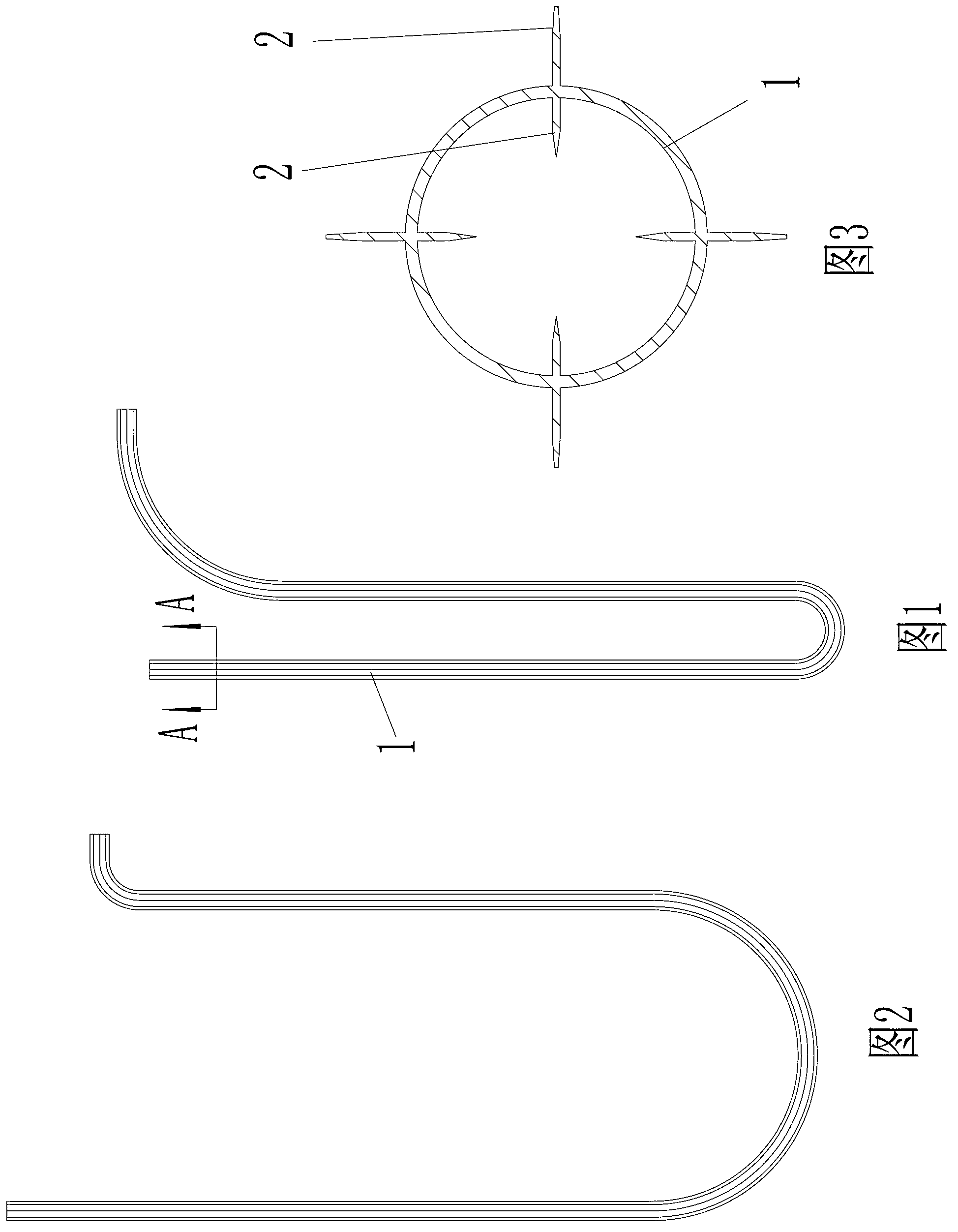
[0016] As shown in the figure, the heat conduction pipe of the exhaust gas waste liquid waste heat recovery device provided by the present invention includes a pipe body 1 made of metal material (the diameter of the pipe is usually more than 20mm, the thickness of the pipe wall is usually 0.5-3.5mm, and the length depends on the heat Recycling needs to be determined); it is characterized in that several heat conducting fins 2 are made on the inner wall surface and the outer surface of the pipeline body, and the thickness is usually 0.5-3mm; these heat conducting fins are integrated with the pipeline body, and are along the The length direction of the pipeline body is continuously extended; since the direction of the heat conduction sheet on the surface of the inner wall is consistent with the flow direction of the medium (gas or liquid medium) in the heat conduction tube, it will not hinder the movement of the medium.

[0017] like image 3 Shown: The heat conduction sheet is ...


PUM


Abstract

The invention relates to a heat conduction pipe of a waste gas and waste fluid waste heat recovery device. The heat conduction pipe solves the technical problems that the heat conduction pipe has the characteristics of high heat absorption efficiency and high heat transmission efficiency, and the obvious energy-saving benefits are obtained. The technical scheme is that the heat conduction pipe of the waste gas and waste fluid waste heat recovery device comprises a pipeline body made of a metal material, the heat conduction pipe is characterized in that the inner wall surface and the outer wall surface of the pipeline body are respectively provided with a plurality of heat conducting fins, and the heat conducting fins are connected with the pipeline body into a whole and can serially expand along a length direction of the pipeline body; the central lines of the cross sections of the heat conducting fins are distributed along the semidiameter of the pipeline body, and the central lines of the heat conducting fins of the inner wall surface and the central lines of the heat conducting fins of the outer wall surface are coincident; the number of the heat conducting fins of the inner wall surface and the number of the heat conducting fins of the outer surface are respectively four, and the pipeline body is bent to be in an S shape or a U shape; and the metal material is an aluminium product.

Description

technical field [0001] The invention relates to a waste gas heat energy or waste liquid heat energy recovery device component, especially a heat exchange tube of the waste heat recovery device, which is especially suitable for heat energy recovery of high-calorie waste gas of printing machines, hot air dryers and other equipment. Background technique [0002] The gravure printing machine is generally composed of more than 3 color groups, and each color group is equipped with one or two sets of ovens according to production requirements, so as to quickly dry the ink printed on the surface of the roll material (such as printing paper) at high speed. The oven generally uses thermal energy such as electric heat conduction oil and gas to heat the air to a certain temperature (100°C-200°C), and then blows high-temperature gas to the printing surface of the coil to dry the printed ink quickly; The exhaust gas with water vapor is pumped out of the oven to ensure the printing quality...

Claims


Application Information

Patent Timeline
Patent Type & Authority Applications(China)
IPC IPC(8): F28F1/42
Inventor 刘国方
Owner ZHEJIANG MEIGE MACHINERY
Why Eureka
Try Eureka