Camshaft module

A technology of camshafts and modular bodies, applied in the direction of valve devices, housings, machines/engines, etc., capable of solving impossible problems

Inactive Publication Date: 2018-01-05
THYSSENKRUPP PRESTA TECCENTER AG +1
View PDF9 Cites 0 Cited by
  • Summary
  • Abstract
  • Description
  • Claims
  • Application Information

AI Technical Summary

Problems solved by technology

Here, it is technically possible to select the same material for the support element and the cylinder head, but such a technical possibility as described above is not possible with existing types of camshaft modules

Method used


Image

  • Camshaft module
  • Camshaft module
  • Camshaft module

Examples


Embodiment Construction

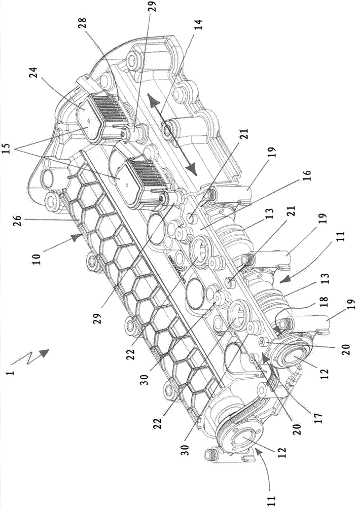
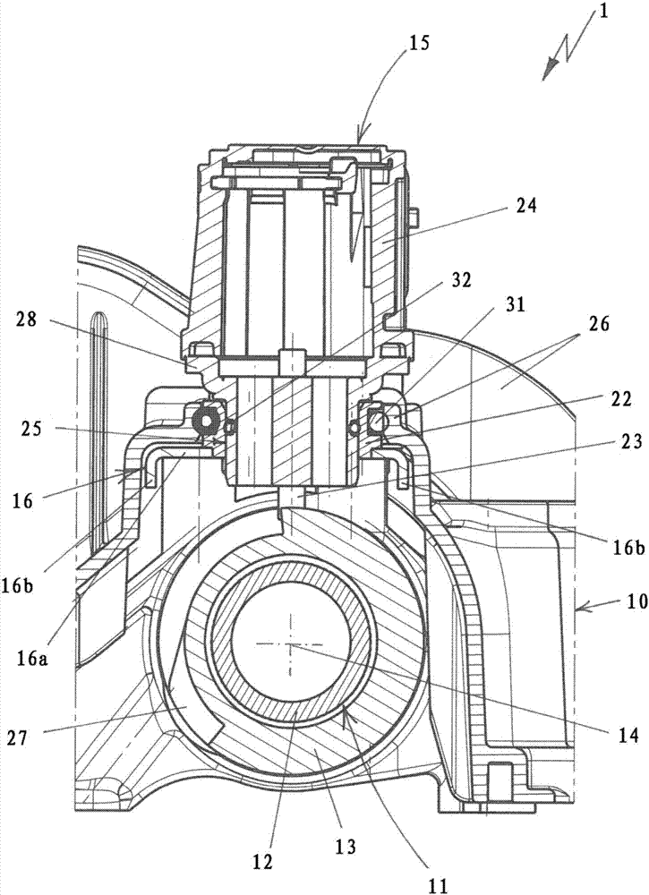
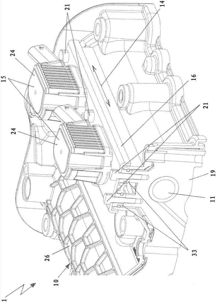
[0028] figure 1 A perspective view is shown of a camshaft module 1 with a module body 10 in which two camshafts 11 for controlling valves for a charging cycle of an internal combustion engine are accommodated. The camshaft module 1 is intended in particular for mounting on a cylinder head of an internal combustion engine.

[0029] The module body 10 has a cover 26 and on the underside of the cover 26 a plurality of bearing bridges 19 connected to the cover 26 are arranged. The camshaft 11 is rotatably accommodated on the module body 10 by means of a bearing bridge 19 . The camshafts 11 each have a support shaft 12 , and a plurality of slide cam pieces 13 are accommodated to be movable in an axial direction 14 on each of the support shafts 12 . In order to change the axial position of the sliding cam elements 13, actuators 15 are assigned to the corresponding sliding cam elements 13, wherein, for the shown camshaft module 1, four actuators 15 are provided, but only shown Two...


PUM


Abstract

The present invention relates to a camshaft module, (1) having a module body (10), in which at least one camshaft (11) is accommodated for controlling valves for the load change of an internal combustion engine, the camshaft (11) comprising a support shaft (12) and a plurality of sliding cam pieces (13) which are slidably received on the support shaft (12) in the axial direction (14) of the support shaft (12). According to the invention, a support element (16) is provided, on which actuators (15) can be received for the axial displacement of the sliding cam pieces (13), the support element (16) extending in the axial direction (14) and thus parallel to the support shaft (12).

Description

technical field [0001] The invention relates to a camshaft module having a module body in which at least one camshaft for controlling valves for a charging cycle of an internal combustion engine is accommodated, wherein the camshaft comprises a bearing shaft and a plurality of A sliding cam piece, the plurality of sliding cam pieces are accommodated on the support shaft so as to be displaceable in an axial direction of the support shaft. Background technique [0002] A camshaft module of the type in question is known, for example, from DE 10 2011 111 580 A1. The camshaft module has a module body, and the module body basically consists of a cover and a plurality of bearing bridges for rotatably accommodating two camshafts. Housed in the housing are actuators which, when properly actuated, are capable of axially adjusting a sliding cam member shown on the support shaft. The cover of the module body is usually formed from aluminum or a special plastic material. In contrast, ...

Claims


Application Information

Patent Timeline
Patent Type & Authority Applications(China)
IPC IPC(8): F01L13/00F01L1/053
CPCF01L1/053F01L13/0036F01L2001/0476F01L2001/0537F01L2013/0052F01L2013/101F01L2301/00F01L2820/01F01L1/46F01L2001/0473F01L2013/0078F02F7/006F02F2007/0063
Inventor 于尔根·莫伊泽尔
Owner THYSSENKRUPP PRESTA TECCENTER AG
Why Eureka
Try Eureka