A garment template machine

A template machine and movable plate technology, which is applied in the direction of cloth feeding mechanism, sewing machine components, textiles and paper making, etc., can solve the problems that the template shell cannot be fixed, the waste of resources is rationally used, and the tools cannot be placed on the workbench, etc.

Active Publication Date: 2020-10-27
阜阳鑫合服饰有限公司
View PDF8 Cites 0 Cited by
  • Summary
  • Abstract
  • Description
  • Claims
  • Application Information

AI Technical Summary

Problems solved by technology

[0003] There are certain disadvantages in the use of the existing garment template machine, (1), when the existing garment template machine is in use, it does not have the function of a tool placement table, and the tool cannot be placed on the workbench. When using a tool, you can only place the tool by purchasing a cart, which affects the use of the tool by the processing personnel to a certain extent, and at the same time wastes the rational use of resources; (2). The connecting frame on the top of the table fixes one side of the formwork shell, but not the other side of the formwork shell. When working, the formwork shell needs to move together with the inner fabric. During the movement, the inner fabric is easy to Relative sliding occurs between the shell and the template shell, which affects the sewing accuracy. Therefore, we propose a garment template machine

Method used


Image

  • A garment template machine
  • A garment template machine
  • A garment template machine

Examples


Embodiment 1

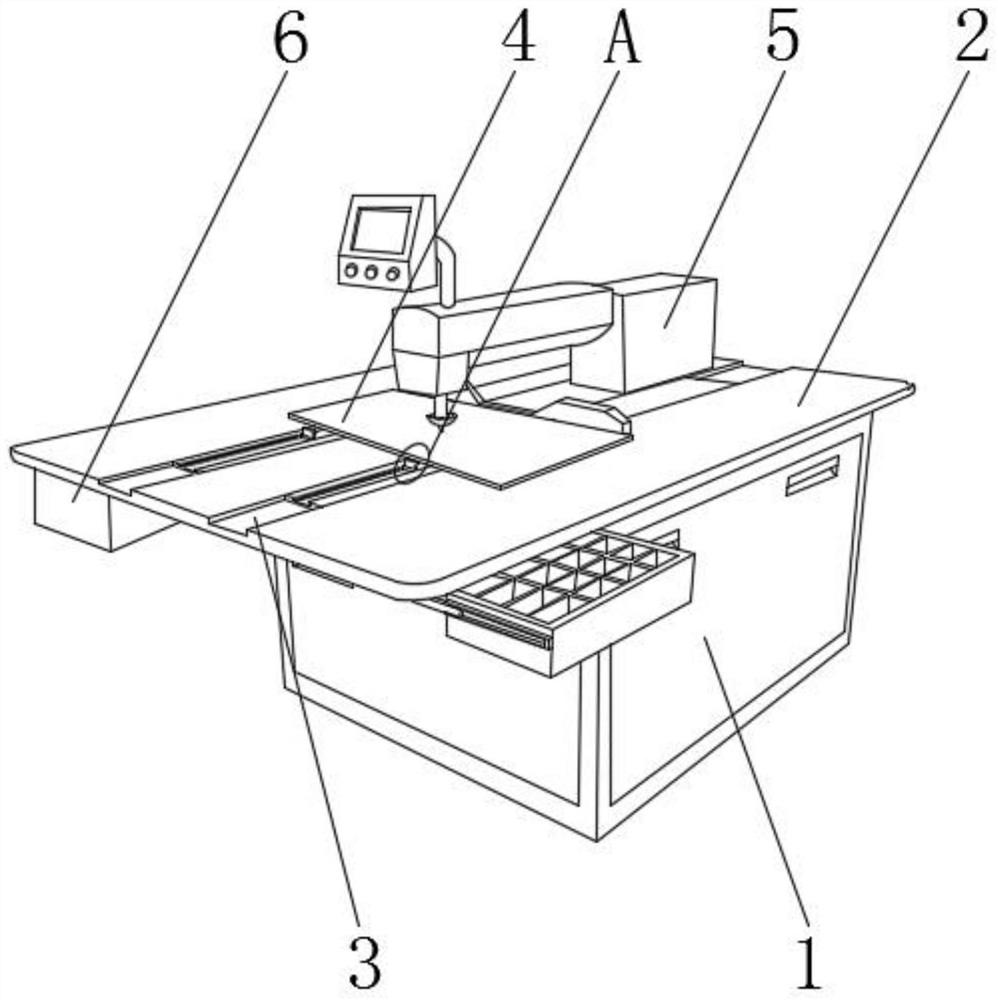
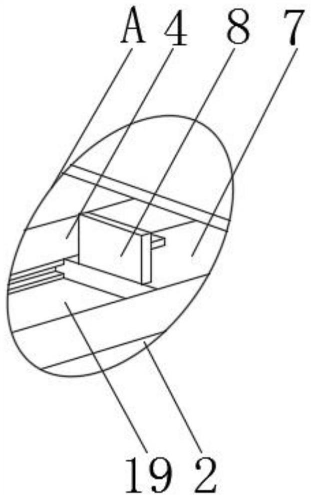
[0029] like Figure 1-3 As shown, the formwork machine base 1 is included, and the outer surface of one side of the formwork machine base 1 is fixed with a protective plate by bolts, and the front end outer surface of the protective plate is provided with a handle near the top position. The surface near the four corners is fixed with support columns by bolts, and the bottom end of the support columns is bonded with a rubber pad. The top outer surface of the template machine base 1 is fixed with a workbench 2 by bolts. The template shell is placed near the position of the sewing machine, and the top outer surface of the workbench 2 is provided with guide grooves 3 near both sides. The inner surface of the guide groove 3 is movably equipped with movable plates 4, and the two groups of movable plates 4 A connecting frame is welded near the outer surface of the top end, the outer surface of the front end of the connecting frame is fixed with a fixing clip by bolts near the bottom ...

Embodiment 2

[0032] like Figure 4 As shown, the outer surfaces on both sides of the storage box 6 are fixed with slide rails 11 near the top position by bolts, and the inner surface of the slide rails 11 is movably equipped with a slide bar 12, between the slide rail 11 and the slide bar 12 A pulley is provided, and the slide rail 11 is movably connected with the slide bar 12 by the pulley, the outer surface of the front end of the slide bar 12 is welded with a connecting rod 13, and the outer surface of the top end of the placement box 6 is provided with a placement groove 14, and the placement groove The inside of 14 is fixed with many sets of dividing plates 15 by bolts.

[0033] By installing the placement box 6, the tool can be stored more conveniently. By installing the slide bar 12 and the slide rail 11 between the two sides of the placement box 6 and the workbench 2, when it needs to be taken or retracted, manually place the When the box 6 is pushed inward or pulled outward, it c...

Embodiment 3

[0036] like Figure 5-7 As shown, the top outer surface of the connecting rod 13 is welded with a connecting shaft 16 close to both sides, and the top outer surface of the connecting shaft 16 is fixed with a rotating shaft 17 by bolts, and the bottom outer surface of the workbench 2 is provided with T-slot 18.

[0037] By installing a slidable connecting shaft 16 on both sides of the top of the connecting rod 13, and then cooperating with the T-shaped groove 18 at the bottom of the workbench 2, when it needs to be moved and used, it is only necessary to manually pull the placement box 6 to one side, and the connecting shaft The rotating shaft 17 at the top of 16 rotates inside the T-shaped slot 18 and moves to one side. When turning, because the two sets of connecting shafts 16 are two points, and the connecting rod 13 is not in the T-shaped slot 18, it will not affect the placement box The normal rotation of 6 can move the placement box 6 more freely and conveniently, improv...


PUM


Abstract

The invention discloses a clothing manufacturing template machine which comprises a template machine base. A working table is fixed to the outer surface of the top end of the template machine base through bolts. Guide grooves are formed in the positions, close to the two sides, of the outer surface of the top end of the working table respectively. A movable plate is movably installed on the innersurface of each guide groove. A control box is fixed to the position, close to the center, of the outer surface of the top end of the working table through bolts. By means of the clothing manufacturing template machine, tools can be more conveniently stored; meanwhile, a placement box can be stored, and the space is prevented from being occupied; the placement box can be more freely and rapidly moved, the activity range of workers is enlarged, the clothing manufacturing template machine can be more conveniently used by workers, and work efficiency is improved; a template shell can be better fixed, it is avoided that the template shell and inner clothing slide relatively during sewing, the sewing precision is better improved, and better use prospects are achieved.

Description

technical field [0001] The invention relates to the field of template machines, in particular to a template machine for garment making. Background technique [0002] The garment template machine is designed to realize high-quality garment design and is used for the production of garment templates. It can turn flexibly at multiple angles to make the size of large, medium and small garments accurate and consistent. At the same time, it reduces the sewing process. It is easy to operate and does not require Training can also operate; [0003] There are certain disadvantages in the use of the existing garment template machine, (1), when the existing garment template machine is in use, it does not have the function of a tool placement table, and the tool cannot be placed on the workbench. When using a tool, you can only place the tool by purchasing a cart, which affects the use of the tool by the processing personnel to a certain extent, and at the same time wastes the rational u...

Claims


Application Information

Patent Timeline
Patent Type & Authority Patents(China)
IPC IPC(8): D05B35/00D05B75/00D05B81/00
CPCD05B35/00D05B75/00D05B81/00
Inventor 黄祖运
Owner 阜阳鑫合服饰有限公司
Why Eureka
Try Eureka