Check patentability & draft patents in minutes with Patsnap Eureka AI!

Synchronous Timing Trigger System and Method Applied to Particle Accelerator

A particle accelerator, synchronous timing technology, applied in time division multiplexing systems, multiplexing communications, electrical components, etc., can solve the problem of low data transmission and real-time performance, unfavorable system expansion, upgrade and optimization, transmission speed Slow and other problems, to solve the conflict of communication ports and resources, reduce the cycle of hardware research and development, improve reliability and synchronization

Active Publication Date: 2020-08-21
INST OF MODERN PHYSICS CHINESE ACADEMY OF SCI
View PDF4 Cites 0 Cited by
  • Summary
  • Abstract
  • Description
  • Claims
  • Application Information

AI Technical Summary

Problems solved by technology

The system can realize the digital pulse power supply of the ion accelerator or multiple digital pulse power supplies in the related industrial fields to start synchronously according to the set time sequence or group timing synchronous start control, which meets the requirements of the digital pulse power supply in the related field in the remote control mode. , but there are some shortcomings in this system: First, the system uses FPGA-based programmable system-on-chip as the trigger source server, and the functions and performance of the system are limited by the performance and resources of the system-on-chip, which is not conducive to system expansion, upgrade and optimization; Second, the system interacts with the upper computer (control computer) through the network chip and network port of the system-on-chip, and uses the TCP / IP communication protocol for data interaction. The data transmission and real-time performance are not high, and the transmission speed is slow; third, due to the The system is connected with other systems based on the TCP / IP communication protocol. When multiple users interact with it, there are problems such as communication port and resource conflicts.

Method used


Image

  • Synchronous Timing Trigger System and Method Applied to Particle Accelerator
  • Synchronous Timing Trigger System and Method Applied to Particle Accelerator
  • Synchronous Timing Trigger System and Method Applied to Particle Accelerator

Examples


Embodiment Construction

[0032] In order to make the object, technical solution and advantages of the present invention clearer, the present invention will be described in further detail below in conjunction with specific embodiments and with reference to the accompanying drawings.

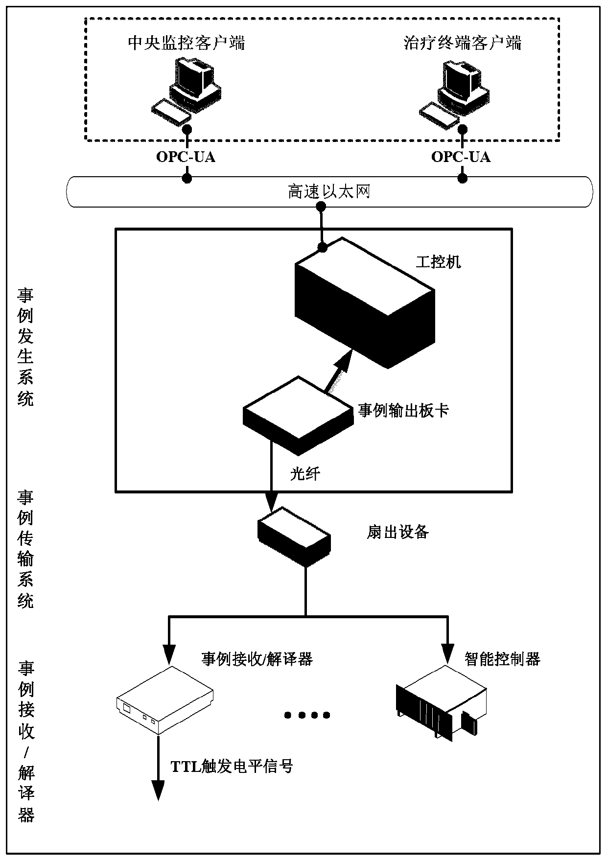
[0033] The embodiment of the present invention proposes a particle accelerator synchronous timing trigger system, which can be connected to at least one client and can provide multi-client access. Its structure is as follows figure 1 shown. The system can be used in medical heavy ion therapy devices. During the treatment process of medical heavy ion therapy devices, the accelerator and all devices that need to be synchronized at the treatment terminal are triggered synchronously and regularly, and run synchronously with a precise time base to generate the particle beams required for treatment. Its structure includes a case generation system, a case transmission system and a case receiver / interpreter, wherein the case tran...


PUM


Abstract

The invention provides a synchronous timing trigger system applied to particle accelerators, comprising: a case generation system, used to index case files from a database according to case file numbers, and output case light signals according to case files; a case transmission system, used to transfer case Optical signal; case receiver / interpreter, used to receive the case light signal and convert it into case code, compare the case code with the trigger case code stored in the case receiver / decoder, if the two case codes are consistent, then generate the trigger signal or level, to trigger the device. The system adopts the PXIe / PXI industrial computer + case output board hardware solution to solve the problem of insufficient computing functions and storage resources of the system on chip, and improve the system control accuracy and speed; the controller and the case output board are connected through a high-speed backplane bus. Data interaction ensures the speed of data transmission and improves the real-time performance, reliability and synchronization of the system; it can provide multi-client access and solve the problems of communication ports and resource conflicts.

Description

technical field [0001] The invention relates to the technical field of tumor radiotherapy, in particular to a synchronous timing trigger system and method applied to particle accelerators. Background technique [0002] The medical heavy ion accelerator is an important component of the medical heavy ion therapy device. The object controlled by the accelerator is the charged particles running at a high speed close to the speed of light in the vacuum tube. In the process of medical heavy ion therapy, all the devices that need to be synchronized in the accelerator and the treatment terminal are required to operate synchronously with a precise time base, which requires a set of high-precision synchronous timing trigger system to coordinate and coordinate all the devices that need to be synchronized. Command and dispatch, operate synchronously according to strict cycle and timing, and generate particle beams required for treatment. [0003] At present, the synchronous timing trig...

Claims


Application Information

Patent Timeline
Patent Type & Authority Patents(China)
IPC IPC(8): H04J3/06
CPCH04J3/0658H04J3/0682
Inventor 杨锋张玮王强杨旗安石王鹏鹏
Owner INST OF MODERN PHYSICS CHINESE ACADEMY OF SCI
Features
  • R&D
  • Intellectual Property
  • Life Sciences
  • Materials
  • Tech Scout
  • Unparalleled Data Quality
  • Higher Quality Content
  • 60% Fewer Hallucinations
Learn More