Light-dimming driving circuit of LED lamp, light-dimming driving chip and control circuit

A technology of dimming drive and LED lights, applied in the field of lighting, can solve problems such as large audio noise, small dimming range, poor dimming performance of LED lights, etc.

Active Publication Date: 2019-03-15
SHENZHEN WINSEMI MICROELECTRONICS
View PDF6 Cites 3 Cited by
  • Summary
  • Abstract
  • Description
  • Claims
  • Application Information

AI Technical Summary

Problems solved by technology

[0006] In view of this, the embodiment of the present invention provides a dimming driving circuit for LED lamps, a dimming driving chip for LED lamps, and a control circuit for LED loads, aiming to solve

Method used


Image

  • Light-dimming driving circuit of LED lamp, light-dimming driving chip and control circuit
  • Light-dimming driving circuit of LED lamp, light-dimming driving chip and control circuit
  • Light-dimming driving circuit of LED lamp, light-dimming driving chip and control circuit

Examples


Embodiment Construction

[0047] In order to make the objectives, technical solutions and advantages of the present invention clearer, the following further describes the present invention in detail with reference to the accompanying drawings and embodiments. It should be understood that the specific embodiments described herein are only used to explain the present invention, but not to limit the present invention.

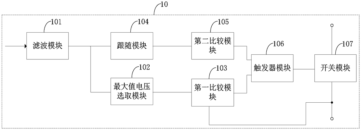
[0048] figure 1 The module structure of the dimming driving circuit 10 of the LED lamp provided by the embodiment of the present invention is shown. For ease of description, only the parts related to the embodiment of the present invention are shown, and the details are as follows:

[0049] Such as figure 1 As shown, the dimming driving circuit 10 includes: a filter module 101, a maximum voltage selection module 102, a first comparison module 103, a follower module 104, a second comparison module 105, a trigger module 106, and a switch module 107.

[0050] Wherein, the filter module 101 connects ...


PUM


Abstract

The invention discloses a light-dimming driving circuit of an LED lamp, a light-dimming driving chip of the LED lamp, and a control circuit loaded by the LED. The light-dimming driving circuit comprises a filter module, a maximum voltage selection module, a first comparison module, a follower module, a second comparison module, a trigger module and a switch module; the filter module filters the analog voltage signal to obtain the DC voltage; the maximum voltage selection module obtains the maximum between the first reference voltage and the DC voltage; the first comparison module outputs a first reset signal or a second reset signal according to sampling voltage and the voltage output by the maximum voltage selection module; the follower module outputs the first low-resistance voltage andthe second low-resistance voltage according to DC voltage; the second comparison module outputs a first pulse signal or a second pulse signal according to the voltage output by the follower circuit and a second reference voltage. The light-emitting state of the LED lamp can be changed in real time through the first reset signal, the second reset signal, the first pulse signal and the second pulsesignal.

Description

Technical field [0001] The invention belongs to the field of lighting technology, and in particular relates to a dimming drive circuit of an LED lamp, a dimming drive chip of an LED lamp and a control circuit of an LED load. Background technique [0002] As a common electronic component, LED (Light Emitting Diode) lamps have been widely used in various industrial and technical fields due to their low manufacturing costs and better light-emitting effects; traditional technologies have been driven by corresponding drive circuits. Ground on or off state to control the luminous effect of the LED light, so that the LED light can change its own light-emitting state according to the actual needs of the user; the LED light will also be realized when the LED light is connected to the external power supply Its own energy storage. When the power supply connected to the LED lamp is in a critical continuous state, the electric energy stored by the LED lamp itself will also fluctuate greatly. ...

Claims


Application Information

Patent Timeline
IPC IPC(8): H05B33/08H05B44/00
CPCH05B45/00H05B45/37
Inventor 宋利军戴小梅
Owner SHENZHEN WINSEMI MICROELECTRONICS
Why Eureka
Try Eureka