
Intelligent power-assisted electric stimulation system

A technology of stimulating electrodes and stimulating signals, which is applied in the field of medical electronics and can solve problems such as out-of-step, involuntary awareness, and ineffective effects

Inactive Publication Date: 2019-03-19
HANGZHOU CHENGNUO MEDICAL SCI & TECH CO LTD
View PDF4 Cites 0 Cited by
  • Summary
  • Abstract
  • Description
  • Claims
  • Application Information

AI Technical Summary

Problems solved by technology

Passive functional electrical stimulation is to pre-set the stimulation current intensity and stimulation time. During the stimulation process, the stimulation current remains unchanged, and the stimulation treatment in the interval is stopped. A period of time is customized for this treatment. The user accepts the treatment passively, without self-consciousness and active contraction throughout , action; trigger-type functional electrical stimulation adds myoelectric feedback on the basis of passive functional electrical stimulation. When the value of the feedback electrical signal exceeds the previously predetermined threshold value, electrical stimulation starts. When the stimulation current and stimulation time are stimulated according to the previous predetermined value, the user actively Participate in passive training, the stimulation current and stimulation time do not change during the stimulation process, and cannot reflect the user's subjective consciousness after triggering
[0004] Generally speaking, after the existing functional electrical stimulation is triggered, the electrical stimulation has nothing to do with the user's subjective will, and the stimulation operates according to the previously set mode, which is not in sync with the action the user wants to do, and the effect is not obvious , improper operation may even have a counterproductive effect

Method used


Image

  • Intelligent power-assisted electric stimulation system
  • Intelligent power-assisted electric stimulation system

Examples


Embodiment Construction

[0017] In order to make the object, technical solution and advantages of the present invention clearer, the present invention will be further described in detail below in conjunction with the accompanying drawings and embodiments. It should be understood that the specific embodiments described here are only used to explain the present invention, not to limit the present invention.

[0018] On the contrary, the invention covers any alternatives, modifications, equivalent methods and schemes within the spirit and scope of the invention as defined by the claims. Further, in order to make the public have a better understanding of the present invention, some specific details are described in detail in the detailed description of the present invention below. The present invention can be fully understood by those skilled in the art without the description of these detailed parts.

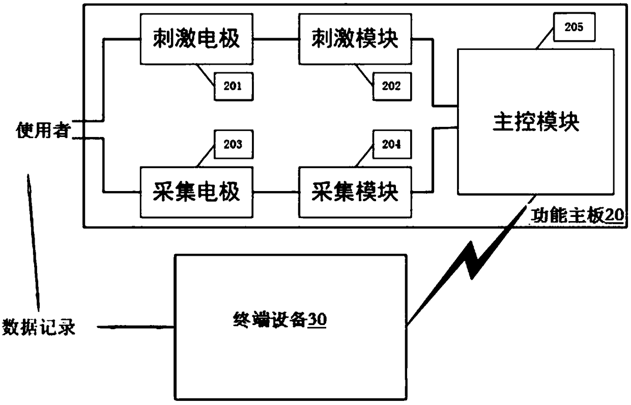
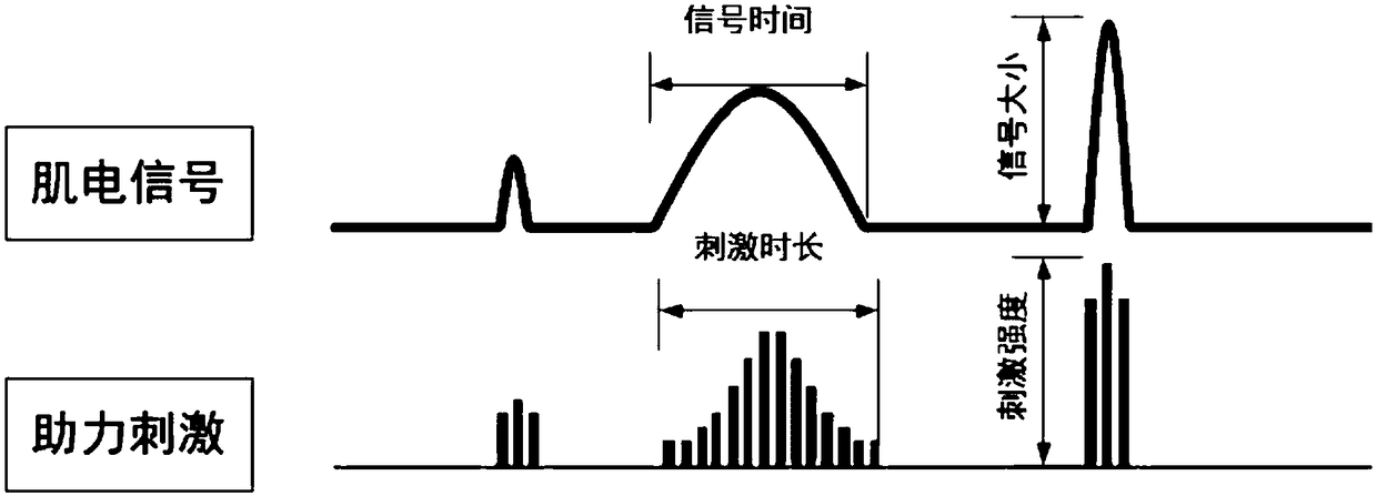
[0019] see figure 1 , 2 , shows a structural block diagram and related waveform diagrams of an intel...


PUM


Abstract

The invention discloses an intelligent power-assisted electric stimulation system. The system comprises a functional main board and terminal equipment; the functional main board comprises a stimulation electrode, a stimulation module, a main control module, a collection electrode and a collection module, the stimulation electrode and the collection electrode are connected with an action part separately, and the main control module controls the stimulation electrode to output stimulation current through the stimulation module; the main control module obtains a signal collected by the collectionelectrode through the collection module, processes the signal and feeds the signal back to the stimulation module, and the stimulation current is output through the stimulation electrode. By means ofthe system, the magnitude of the myoelectric signal is collected according to high-speed and high-precision myoelectric sampling, the system self-adaptively gives corresponding strong and weak electrical stimulation, the willingness and requirement of a user for subjective motion are completely reflected in real time, and the user is helped to complete the action which he / she wants to complete.

Description

technical field [0001] The invention belongs to the field of medical electronics and relates to an intelligent power-assisted electrical stimulation system. Background technique [0002] Functional electrical stimulation (FES) belongs to the category of neuromuscular electrical stimulation (NES), which uses a certain intensity of low-frequency pulse current to stimulate one or more groups of muscles through a preset program. Induce muscle movement or simulate normal voluntary movement to achieve the purpose of improving or restoring the function of the stimulated muscle or muscle group. [0003] Existing functional electrical stimulation mainly includes passive functional electrical stimulation and triggered functional electrical stimulation. Passive functional electrical stimulation is to pre-set the stimulation current intensity and stimulation time. During the stimulation process, the stimulation current remains unchanged, and the stimulation treatment in the interval is...

Claims


Application Information

Patent Timeline
Patent Type & Authority Applications(China)
IPC IPC(8): A61N1/36
CPCA61N1/36003A61N1/36014A61N1/36031
Inventor 马玉龙李浩余容英
Owner HANGZHOU CHENGNUO MEDICAL SCI & TECH CO LTD
Learn More