Unlock instant, AI-driven research and patent intelligence for your innovation.

Full-automatic powder forming machine

A powder molding machine, fully automatic technology, applied in the direction of material molding presses, presses, conveyor objects, etc., can solve the problems of easily damaged parts, high manual operation intensity, and short service life, and achieve automatic wear and tear. The effect of reducing the intensity of manual operation and improving the yield of the piercing rod

Pending Publication Date: 2019-03-19
东莞市新日宝成形机器设备有限公司
View PDF0 Cites 0 Cited by
  • Summary
  • Abstract
  • Description
  • Claims
  • Application Information

AI Technical Summary

Problems solved by technology

[0003] 1. The existing powder compaction molding machine has high punching strength and weak bearing capacity, which is easy to cause instability, and the consumption caused by punching is too large, the parts are easy to be damaged, and the service life is not long;
[0004] 2. The formed pressed parts are only stacked in the collection box. For subsequent processing, it is necessary to manually sort them one by one, especially when pressing ring-shaped workpieces, it is necessary to manually insert the ring-shaped workpieces into the piercing rod one by one. Formed in strings, the manual operation is intensive, the waste rate of rod threading is high, the labor intensity is high, and the production efficiency is limited

Method used


Image

  • Full-automatic powder forming machine
  • Full-automatic powder forming machine
  • Full-automatic powder forming machine

Examples


Embodiment Construction

[0024] The present invention will be further described below in conjunction with the accompanying drawings.

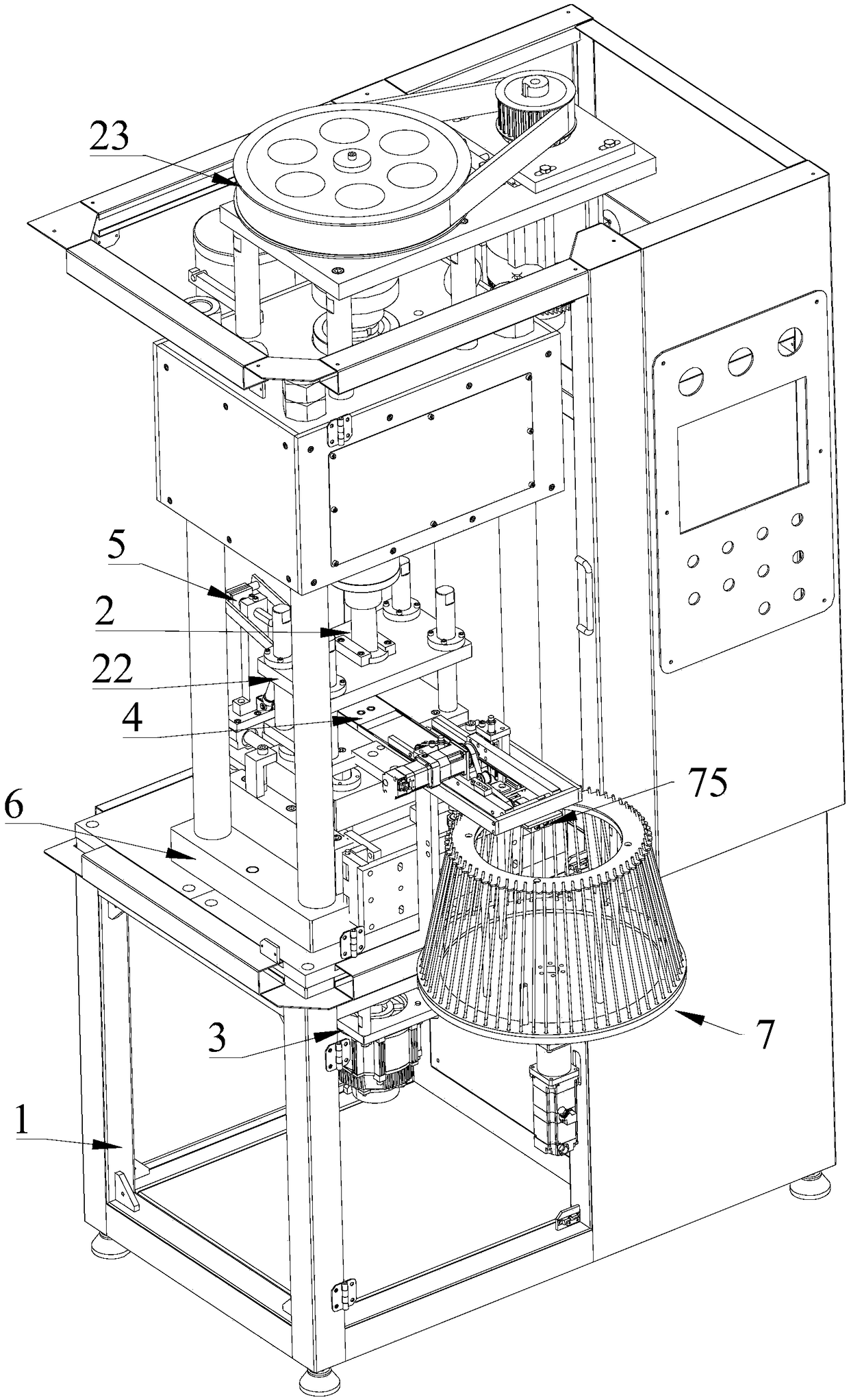
[0025] refer to Figure 1 to Figure 4 , a full-automatic powder molding machine, comprising a machine base 1, an upper punch device 2, a lower punch device 3, a mold device 4 and a pushing device 5, the upper punch device 2 and the lower punch device 3 are respectively located in the mold device 4 The upper and lower sides are pressed to form a ring-shaped workpiece, and the pushing device 5 is installed on one side of the mold device 4 to push out. This embodiment also includes a load-bearing installation seat 6 and a sheet-threading device 7, and the load-bearing installation seat 6 is installed on the machine base 1 , the mold device 4 is fixedly installed on the load-bearing mounting seat 6, and the sheet threading device 7 can be installed on one side of the mold device 4. The sheet threading device 7 is provided with a suction transfer mechanism 71 and several th...


PUM


Abstract

The invention relates to a full-automatic powder forming machine which comprises a machine base, an upper punch device, a lower punch device, a die device, a material push device, a load bearing installation seat and a piece penetrating device. The upper punch device and the lower punch device are located on the upper side and the lower side of the die device for pressing, and a ring-shaped workpiece is formed. The material push device is arranged on one side of the die device for pushing. The load bearing installation seat is arranged on the machine base. The die device is fixedly arranged onthe load bearing installation seat. The piece penetrating device can be arranged on one side of the die device. The piece penetrating device is provided with an absorbing transferring mechanism and multiple penetrating rods, and the absorbing transferring mechanism moves back and forth between the die device and the multiple bar penetrating rods so that the ring-shaped workpiece can be sent intothe penetrating rods. Compared with the prior art, the piece penetrating device is additionally arranged, the automatic material penetrating action is achieved, an existing manual material penetratingmanner is changed, the manual operation intensity is lowered, the rod penetrating yield is increased, and the production efficiency is higher; and in addition, the load bearing installation seat is additionally arranged on the machine base, larger impact force can be borne, and the use performance is stable.

Description

technical field [0001] The invention relates to the technical field of molding machines, in particular to an automatic powder molding machine. Background technique [0002] The powder compacting machine is a device that uses external pressure to press the powder into the mold device. The existing powder compacting machine is mainly composed of powder loading, pressing and demolding. Usually, the powder compacting machine includes a frame and an upper punching device. , the lower punching device and the mold device, the mold device is provided with one or more mold cavities, the powder material can be filled into the mold cavity, and pressed by the upper punching device and the lower punching device to form a pressed part, and the formed pressed part is pushed out to In the collection box, the existing powder compacting machine has the following defects: [0003] 1. The existing powder compaction molding machine has high punching strength and weak bearing capacity, which is ...

Claims


Application Information

Patent Timeline
IPC IPC(8): B30B11/04B30B15/02B30B15/04B30B15/06B30B15/32B65G47/90
CPCB65G47/90B30B11/04B30B15/022B30B15/04B30B15/065B30B15/32
Inventor 饶俊华尧巍华
Owner 东莞市新日宝成形机器设备有限公司