Loading and unloading equipment

A technology for loading and unloading equipment and installation parts, which is used in lifting devices, transportation and packaging, and stacking of objects. Palletizing operation, no damage to products and packaging, the effect of increasing the flexibility of movement

Pending Publication Date: 2019-03-19
佛山市南海区凯力五金制品有限公司
View PDF0 Cites 4 Cited by
  • Summary
  • Abstract
  • Description
  • Claims
  • Application Information

AI Technical Summary

Problems solved by technology

However, the existing manipulator operation method still has deficiencies in the operation of handling and placing goods. For example, the working mode of the vacuum suction cup can often hold a small weight of goods, and due to the limitation of the manipulator's own structure, it is difficult to effectively meet the needs of customers with different specifications. The handling requirements of the goods, if the manipulator for handling the goods cannot adapt to the goods of various specifications, such as different weights and shape widths of the goods, it is very easy to cause damage and scratches to the goods and the surface of the outer packaging when the goods are clamped and transported Even hurt itself, the way of vacuum holding the goods is more likely to damage the surface of the goods and damage the fragile outer packaging
On the other hand, it is difficult for factory shelves to provide sufficient space between goods or boxes to achieve fast and convenient palletizing operations. Therefore, higher requirements are placed on the manipulator function of palletizing operations

Method used


Image

  • Loading and unloading equipment
  • Loading and unloading equipment
  • Loading and unloading equipment

Examples


Embodiment Construction

[0024] Embodiments of the present invention are described in detail below, examples of which are shown in the drawings, wherein the same or similar reference numerals denote the same or similar elements or elements having the same or similar functions throughout. The embodiments described below by referring to the figures are exemplary only for explaining the present invention and should not be construed as limiting the present invention.

[0025] In describing the present invention, it should be understood that the terms "center", "longitudinal", "transverse", "length", "width", "thickness", "upper", "lower", "front", " Orientation indicated by rear, left, right, vertical, horizontal, top, bottom, inside, outside, clockwise, counterclockwise, etc. The positional relationship is based on the orientation or positional relationship shown in the drawings, which is only for the convenience of describing the present invention and simplifying the description, rather than indicating ...


PUM


Abstract

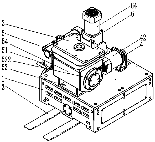
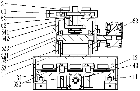
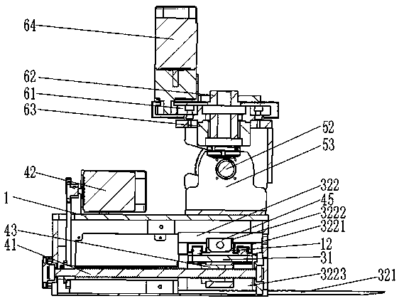
The invention provides loading and unloading equipment. The loading and unloading equipment comprises a first outer shell, a mounting part, an insertion jaw module and a distance adjusting mechanism;and the distance adjusting mechanism is used for adjusting an effective support width value of the insertion jaw module and driving the insertion jaw module to extend out of the first outer shell andto totally shrink in the first outer shell. The loading and unloading equipment with a fork (called the insertion jaw module) is provided to a common manipulator and gantry manipulator production linefor inserting in the bottoms of products to carry and stack the products. The extension length and width of the fork are adjusted according to the lengths and the widths of carried goods. When the loading and unloading equipment is mounted on a carrying robot, the fork supports the goods to shift in an appointed position; and when the fork is descended to enable the bottom to leave from the surfaces of the lower goods by 2-3 cm, the fork totally shrinks into the outer shell to gradually lose a support effect on the goods, so that the stable and accurate stacking of the goods is realized, goods packages are not damaged, and the goods are flexibly stacked in limited space.

Description

technical field [0001] The invention relates to the technical field of mechanical design, in particular to a loading and unloading device. Background technique [0002] At present, when faced with the demand for handling heavy objects and stacking operations in factories, they generally rely on cargo handling robots and their manipulators. The manipulators usually include two functions, one is to clamp the two sides of the goods, and the other is to pass through The way of vacuum suction cup to realize the handling. However, the existing manipulator operation method still has deficiencies in the operation of handling and placing goods. For example, the working mode of the vacuum suction cup can often hold a small weight of goods, and due to the limitation of the manipulator's own structure, it is difficult to effectively meet the needs of customers with different specifications. The handling requirements of the goods, if the manipulator for handling the goods cannot adapt t...

Claims


Application Information

Patent Timeline
Patent Type & Authority Applications(China)
IPC IPC(8): B65G57/03B66F9/075B66F9/12
CPCB65G57/03B66F9/075B66F9/12
Inventor 周永强周健斌陈永照陈瑞
Owner 佛山市南海区凯力五金制品有限公司
Why Eureka
Try Eureka