
Grinding device with spatial displacement

A mobile device and space technology, applied in grinding drive devices, grinding automatic control devices, grinding machines, etc., can solve the problems of difficulty in improving production accuracy and efficiency, obstacles to enterprise development, and high maintenance costs, so as to improve grinding efficiency and mobile High precision and space flexibility, low cost effect

Pending Publication Date: 2020-09-11
宝鸡云智造科技有限公司
View PDF0 Cites 3 Cited by
  • Summary
  • Abstract
  • Description
  • Claims
  • Application Information

AI Technical Summary

Problems solved by technology

There are many types of commonly used mechanical grinding tools. According to different power devices, they can be divided into two categories: pneumatic grinding tools and electric grinding tools. According to the grinding methods, they can be divided into manual mechanical grinding and robot grinding. , fast speed, and intelligent operation, but the relative disadvantages are high failure rate, high price and high maintenance cost. For some small production enterprises, simple grinding equipment is still used to grind manually. , its production accuracy and efficiency are still difficult to improve, which has certain obstacles to the development of enterprises

Method used


Image

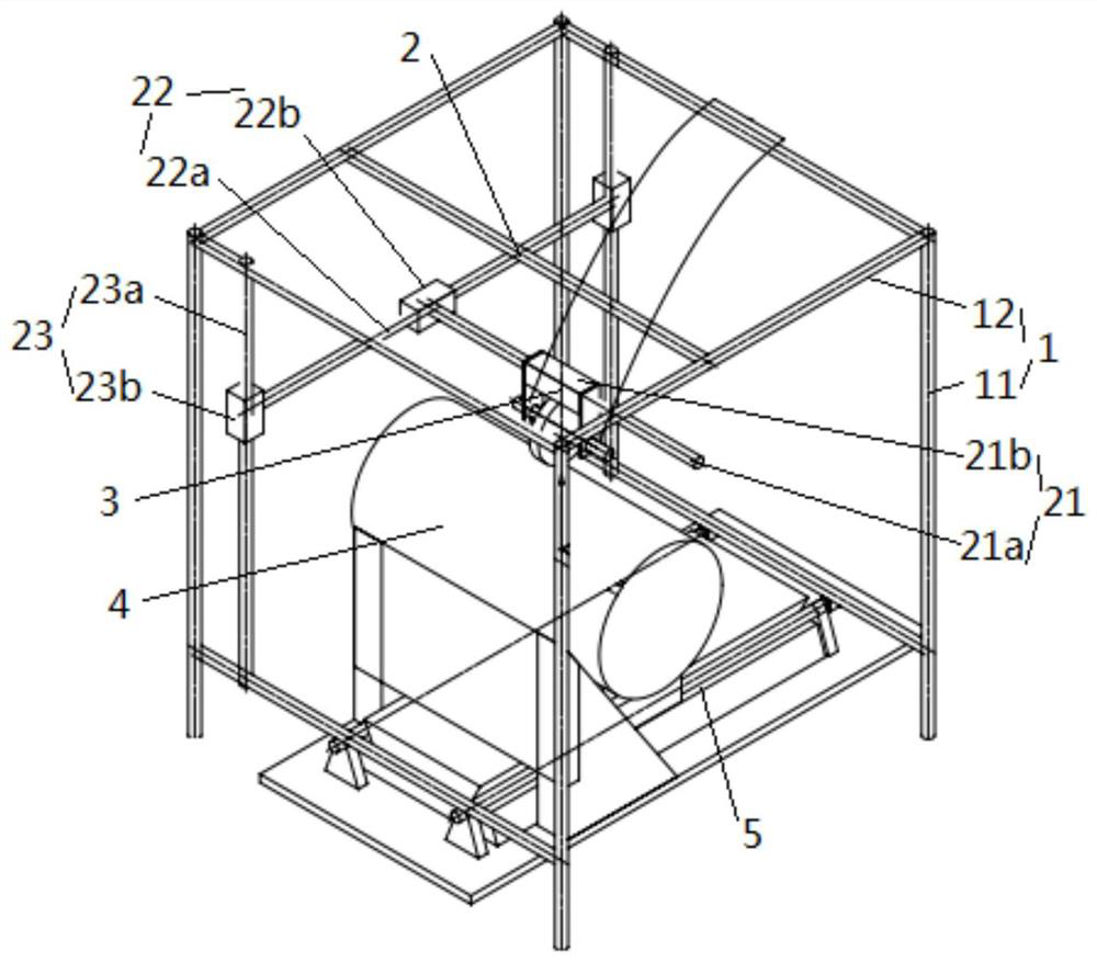
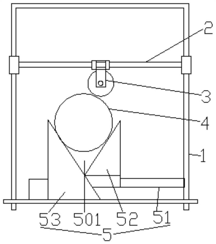
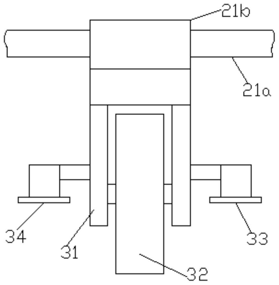
  • Grinding device with spatial displacement
  • Grinding device with spatial displacement
  • Grinding device with spatial displacement

Examples


Embodiment Construction

[0018] In order to enable those skilled in the art to better understand the technical solution of the present invention, the technical solution of the present invention will be further described below in conjunction with the accompanying drawings and embodiments.

[0019] Refer to attached Figure 1~4 The shown grinding device with spatial displacement includes a support frame 1, a spatial displacement mechanism 2 is provided on the support frame 1, and a grinding head identification device 3 is arranged on the spatial displacement mechanism 2, A clamping adjustment mechanism 5 for positioning the workpiece 4 is provided below the grinding head identification device 3 , and both the spatial displacement mechanism 2 and the clamping adjustment mechanism 5 are connected to a control system. The working principle is: place the workpiece 4 on the clamping adjustment mechanism 5, and adjust the position of the workpiece 4 and the height between the workpiece 4 and the grinding head...


PUM


Abstract

The invention discloses a grinding device with spatial displacement. The grinding device comprises a support frame. A spatial displacement mechanism is arranged on the support frame. A grinding head identification device is movably arranged on the spatial displacement mechanism. A clamping and adjusting mechanism for workpiece positioning is arranged below the grinding head identification device.The spatial displacement mechanism and the clamping and adjusting mechanism both are connected with a control system. The grinding device with spatial displacement adopts the frame type structure andhas the beneficial effects of being easy to manufacture, low in cost and stable and reliable; the arranged matched spatial displacement mechanism is simple in structure, high in moving precision and high in space flexibility and is suitable for multi-azimuth grinding operation; the grinding head identification device can accurately identify the position needing to be polished on the surface of a workpiece, the surface-repaired workpiece is identified and ground, the grinding efficiency is improved, and working hours are saved; and the clamping and adjusting mechanism can quickly adjust the position and the height of the workpiece, and the problems that the grinding workpiece is not easy to clamp and is easy to deflect when clamped are solved.

Description

technical field [0001] The invention relates to the technical field of grinding equipment, in particular to a grinding device with spatial displacement. Background technique [0002] Grinding is a kind of surface modification technology. It generally refers to a processing method that uses rough objects (sandpaper with higher hardness particles, etc.) to change the physical properties of the material surface through friction. The main purpose is to obtain a specific surface roughness. There are many types of commonly used mechanical grinding tools. According to different power devices, they can be divided into two categories: pneumatic grinding tools and electric grinding tools. According to the grinding methods, they can be divided into manual mechanical grinding and robot grinding. , fast speed, and intelligent operation, but the relative disadvantages are high failure rate, high price and high maintenance cost. For some small production enterprises, simple grinding equipm...

Claims


Application Information

Patent Timeline
Patent Type & Authority Applications(China)
IPC IPC(8): B24B27/033B24B41/06B24B47/00B24B47/22B24B47/20B24B49/00B24B51/00
CPCB24B27/033B24B41/06B24B49/00B24B51/00B24B47/22B24B47/20B24B47/00
Inventor 王娟平
Owner 宝鸡云智造科技有限公司
Learn More