LED lamp capable of achieving emergency power generation and illumination

A technology for LED lights and emergency power generation, which is applied to semiconductor devices of light-emitting elements, electric light sources, light sources, etc., and can solve problems such as increased weight, large manpower, and inability to continuously generate electricity

Active Publication Date: 2019-03-19
SHANGHAI INST OF TECH
View PDF6 Cites 0 Cited by
  • Summary
  • Abstract
  • Description
  • Claims
  • Application Information

AI Technical Summary

Problems solved by technology

For example, the Chinese patent with the publication number CN104676288A proposes to drive the generator to rotate by turning the handle, which realizes simple operation, but it also requires a lot of manpower.
[0004] 2. Unable to generate power continuously
For example, the Chinese patent with the publication number CN107726234A proposes a method for generating electricity by fixing the rotor of the generator and shaking the stator of the rotating generator. The beneficial effect of the invention is that the structure is simple and labor-saving, but it does not solve the problem of continuous power generation.
[0005] 3. Generally speaking, as the power generation efficiency increases, the size of the power generation module needs to be increased, and the weight also increases relatively. Therefore, the external magnetic force of the rotatable ring that drives the power generation module must also be relatively increased, so larger sizes The power generation module must provide a large magnetic force

Method used


Image

  • LED lamp capable of achieving emergency power generation and illumination
  • LED lamp capable of achieving emergency power generation and illumination
  • LED lamp capable of achieving emergency power generation and illumination

Examples


Embodiment Construction

[0025] The following will combine Figure 1 to Figure 3 The present invention provides a detailed description of an LED lamp that can generate electricity and emit light in an emergency. This embodiment is implemented on the premise of the technical solution of the present invention, and provides a detailed implementation manner and a specific operation process. The protection scope is not limited to the following embodiments, and those skilled in the art can make modifications and improvements within the scope of not changing the spirit and content of the present invention.

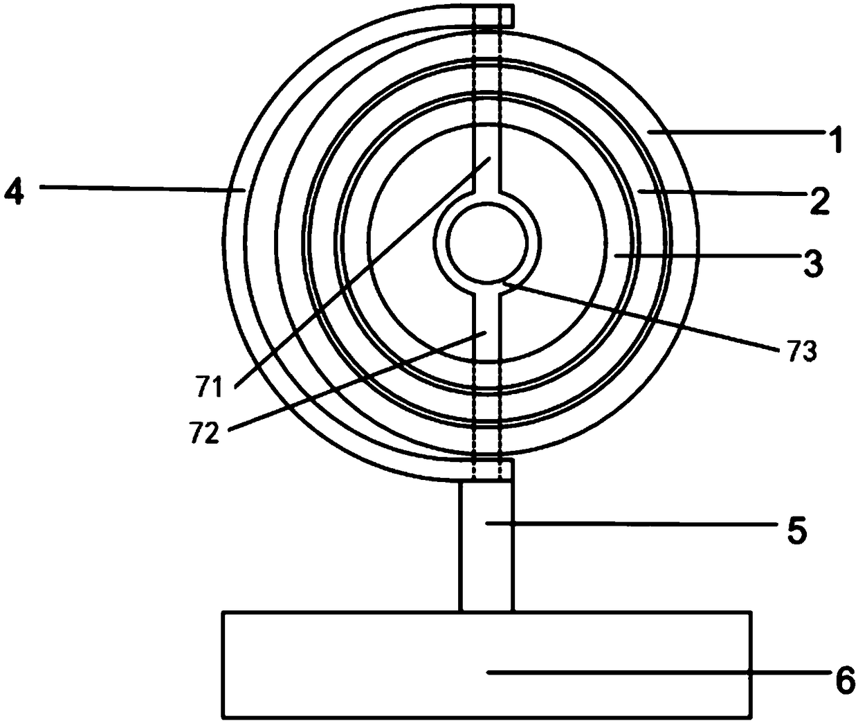
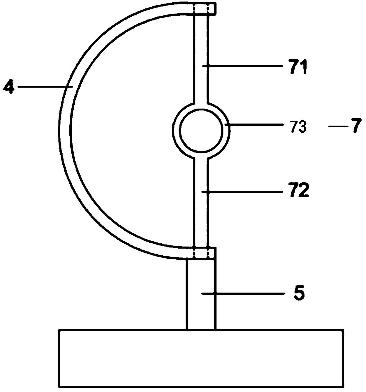
[0026] Please refer to figure 1 and figure 2 , an LED lamp capable of emergency power generation and light emission, comprising a support frame, the support frame includes a hollow base 6, a bottom support column 5, a support column 7 and a semicircular support arm 4, and the bottom support column 5 is fixed and communicated On the base 6 , the support column 7 is fixedly communicated with the bottom ...


PUM


Abstract

The invention relates to an LED lamp capable of achieving emergency power generation and illumination. The LED lamp comprises a supporting frame, the supporting frame comprises a base and a supportingstand column, the supporting stand column is fixedly connected to the base, and a power accumulator is installed in the base. The supporting stand column comprises a hollow upper-section supporting stand column, a hollow fixing circular ring and a hollow lower-section supporting stand column, a multi-turn coil is wound in the fixing circular ring, the head end and the tail end of the coil are electrically connected with two poles of the power accumulator, at least one rotary circular ring is rotationally connected to the supporting stand column, an N pole curved permanent magnet and an S polecurved permanent magnet are installed in the rotary circular ring, and an annular magnetic field is formed between the N pole curved permanent magnet and the S pole curved permanent magnet. The rotary circular ring is rotated, electric energy produced by cutting of the coil in the fixing circular ring in the annular magnetic field is stored in the power accumulator and meet emergencies for the LED lamp on the supporting frame, external power is effectively converted into power energy, and illumination is achieved in the case of a power failure in the way of converting magnetic energy into power energy.

Description

technical field [0001] The invention relates to an LED lamp, in particular to an LED lamp that can generate electricity and emit light in an emergency. Background technique [0002] At present, traditional electric lamps sometimes encounter emergencies and cannot supply power in time, so a product called hand-cranked electric lamp is produced. Most of the hand-cranked generators in the prior art are small-volume and low-power generators. There are many types of hand-cranked electric lamps, including flashlight type, table lamp type, etc., which have the advantages of being household, labor-saving, and simple in structure, but there are still the following problems: [0003] 1. The kinetic energy itself is limited, and a large amount of man-made kinetic energy needs to be converted into the electrical energy required by the lamp. For example, the Chinese Patent Publication No. CN104676288A proposes to drive the generator assembly to rotate by rotating the shaking handle, wh...

Claims


Application Information

Patent Timeline
Patent Type & Authority Applications(China)
IPC IPC(8): F21S9/04F21V23/00F21Y115/10
CPCF21S9/04F21V23/00F21Y2115/10
Inventor 王江张宵宵万文昌李宗桓张晖黄渊博林涛石明明邹军
Owner SHANGHAI INST OF TECH
Why Eureka
Try Eureka