Low light level image intensifier test system

A technology of low-light image intensifier and testing system, which is applied in the direction of optical instrument testing, machine/structural component testing, and optical performance testing. It is convenient for data comparison and statistical analysis, solves the problem of recording depth, and eliminates the effect of measurement error

Active Publication Date: 2019-03-19
NORTH NIGHT VISION TECH
View PDF9 Cites 15 Cited by
  • Summary
  • Abstract
  • Description
  • Claims
  • Application Information

AI Technical Summary

Problems solved by technology

This method uses two different test systems before and after, so the test process may be too complicated and take up more resources. In addition, there may be many problems as follows:
With this method, only one image intensifier can be tested at a time, and the testing efficiency is very low
[0006] 3. The existing input light with different light intensities is selected through filters and shading films with different attenuation. The range of light intensity that can be realized is narrow, and the light can not change linearly, and the light can not be set according to the program. Automatic changes are not conducive to scientific research and testing
However, the failure rate of pinhole printers is high, the whole system is complex and huge, and the recording depth is limited. For example, a few hours of depth recording of the image intensifier will consume a lot of paper
Moreover, the sampling rate of such a test system is low, and it is difficult to capture occasional transient faults
The test data cannot be exported, and subsequent comparison and analysis of the data cannot be performed

Method used


Image

  • Low light level image intensifier test system
  • Low light level image intensifier test system
  • Low light level image intensifier test system

Examples


Embodiment Construction

[0026] In order to make the object, technical solution and advantages of the present invention clearer, the present invention will be further described in detail below with reference to the accompanying drawings and embodiments.

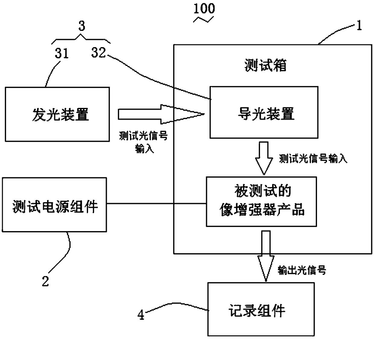
[0027] see figure 1 , a preferred embodiment of the present application provides a low-light image intensifier testing system 100, which can be used for performing performance tests on existing low-light image intensifiers, such as high and low temperature illumination tests. The micro-light image intensifier test system 100 includes a test box 1 , a test power supply component 2 , an illumination component 3 , and a recording component 4 .

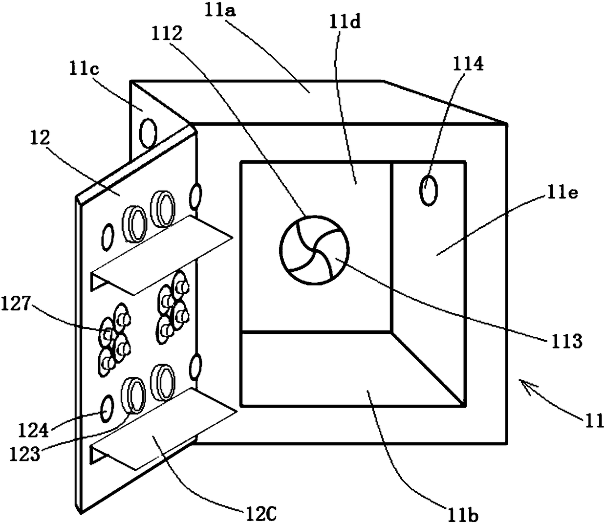
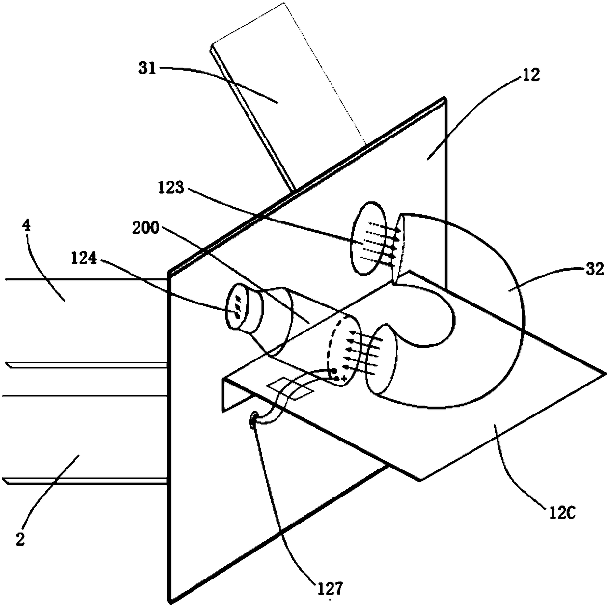
[0028] Please also refer to figure 2 , image 3 and Figure 4, the test box 1 includes a box body 11 and a box door 12, and the box body 11 and the box door 12 are preferably made of light-shielding and insulating materials. The shape of the box body 11 is roughly a rectangular parallelepiped or a cube with...


PUM


Abstract

The invention discloses a low light level image intensifier test system which comprises a test box for containing the tested low light level image intensifier, a test power supply assembly for providing a working power supply to the tested low light level image intensifier, an illumination assembly for providing a test optical signal input to the tested low light level image intensifier, and a recording assembly for receiving an output optical signal generated by the tested low light level image intensifier based on the test optical signal input and converting the output optical signal into atest electrical signal and recording the voltage data of the test electrical signal. The illumination assembly comprises a light emitting device for emitting the test optical signal and a light guidedevice for transmitting the test optical signal; the test power supply assembly, the light emitting device and the recording assembly are all arranged outside the test box, the light guide device is arranged inside the test box and is used for transmitting the test light signal emitted by the light emitting device to the tested low light level image intensifier as the input of the test light signal.

Description

technical field [0001] The invention relates to the field of optoelectronic technology, in particular to a low-light image intensifier test system for performing high and low temperature illumination tests on the low-light image intensifier. Background technique [0002] The low-light image intensifier is mainly composed of a high-voltage power supply and an image intensifier tube. It belongs to a high-voltage electric vacuum device and has important applications in military, scientific research and other fields. Real-world applications often require that the image intensifier can work normally in extreme environments without any problems, so it is necessary to use a test system with variable temperature and variable illumination to test the quality of the image intensifier. [0003] In order to check the quality and reliability of the image intensifier and its high-voltage power supply, in actual production, the high-low temperature test system is usually used to test the h...

Claims


Application Information

Patent Timeline
Patent Type & Authority Applications(China)
IPC IPC(8): G01M11/02
CPCG01M11/00
Inventor 周盛涛杨文波朱文锦李晓露杜培德张昆林褚祝军邓华兵
Owner NORTH NIGHT VISION TECH
Why Eureka
Try Eureka