Test piece load test assembly

A technology of load test and test piece, which is applied in the testing of mechanical components, testing of machine/structural components, and the use of stable tension/pressure to test the strength of materials. and other issues to achieve the effect of ensuring loading accuracy and safety

Inactive Publication Date: 2019-03-19
XIAN AIRCRAFT DESIGN INST OF AVIATION IND OF CHINA
View PDF0 Cites 1 Cited by
  • Summary
  • Abstract
  • Description
  • Claims
  • Application Information

AI Technical Summary

Problems solved by technology

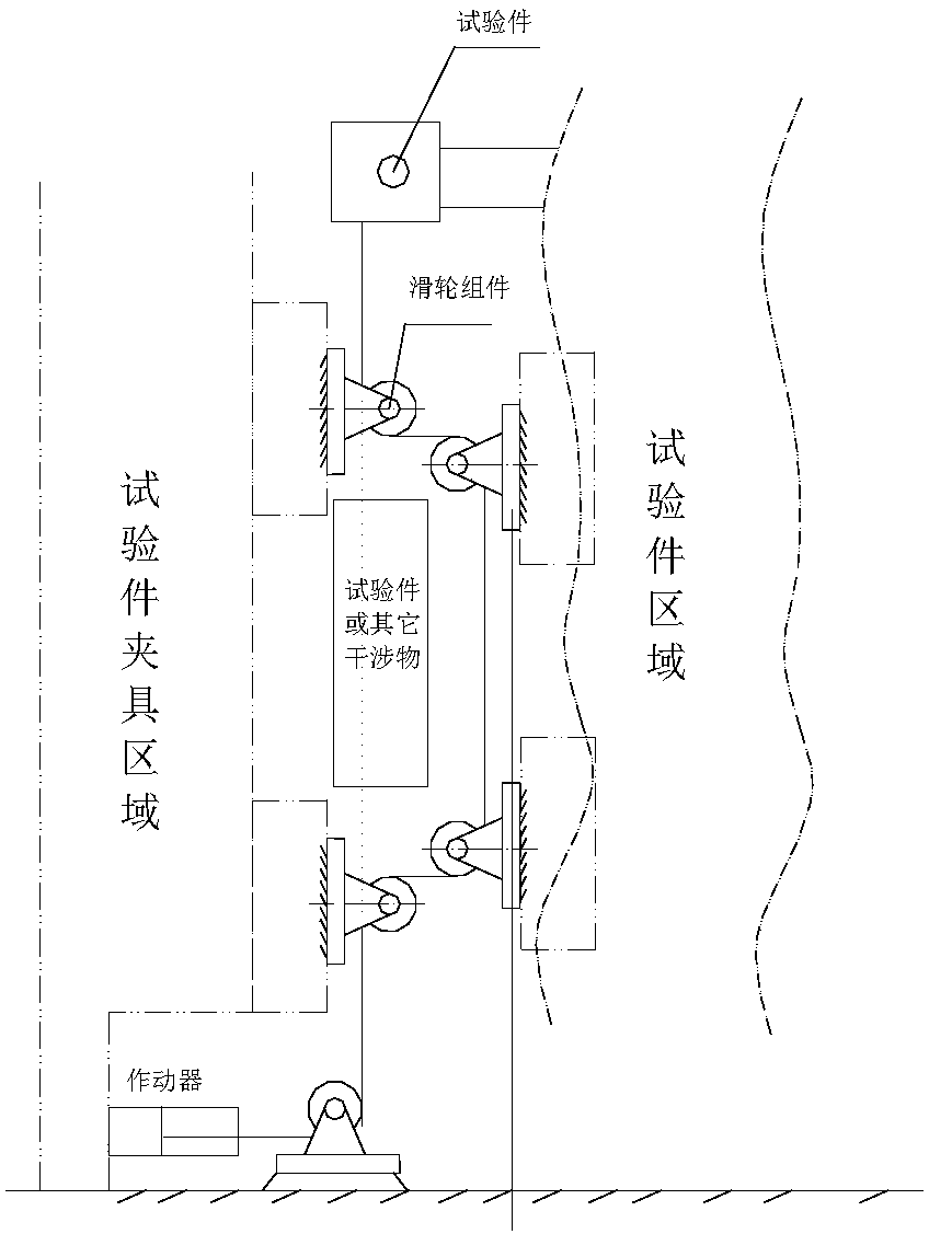
[0002] In the loading test of aircraft structure, a situation that is often encountered is that the linear direction of the loading is different from the loaded part or other unavoidable objects. The existing solutions are as follows: figure 1 As shown, the guide load pulley is used to change the direction of force transmission twice before and after the interference object, but in this way the guide load pulley is equivalent to being in the middle of the loading position, has a certain height and needs to be guided twice, the fixation of the guide load pulley and the balance pulley The clamp for the upper load is difficult to fix and takes up a lot of space. There is only one degree of freedom for adjustment in one direction, and often only one end of the load is controlled. When multi-directional composite loads appear at one end, there is a risk of loss of control

Method used


Image

  • Test piece load test assembly
  • Test piece load test assembly
  • Test piece load test assembly

Examples


Embodiment Construction

[0022] In order to make the objectives, technical solutions and advantages of the present invention clearer, the technical solutions in the embodiments of the present invention will be described in more detail below in conjunction with the drawings in the embodiments of the present invention. In the drawings, the same or similar reference numerals denote the same or similar elements or elements having the same or similar functions throughout. The described embodiments are some, but not all, embodiments of the invention. The embodiments described below by referring to the figures are exemplary and are intended to explain the present invention and should not be construed as limiting the present invention. Based on the embodiments of the present invention, all other embodiments obtained by persons of ordinary skill in the art without creative efforts fall within the protection scope of the present invention. Embodiments of the present invention will be described in detail below ...


PUM


Abstract

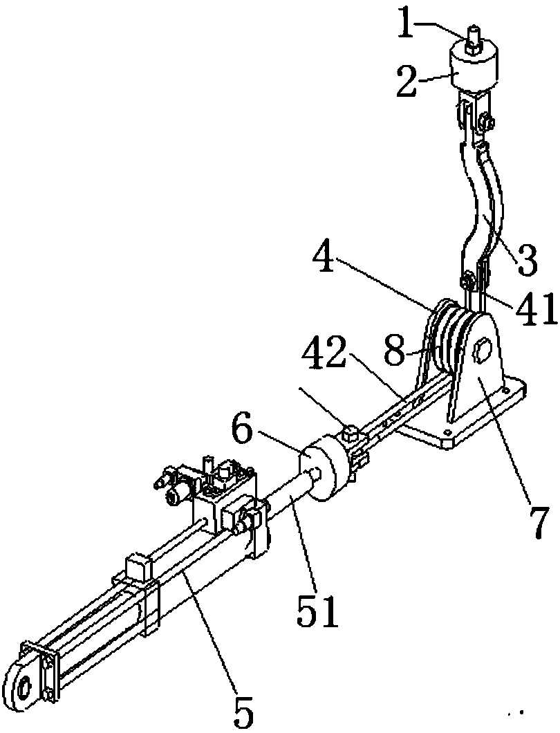
The invention discloses a test piece load test assembly. The test piece load test assembly comprises a connector assembly, a load sensor, a curved load transfer frame, a transmission assembly and an actuator cylinder, wherein one end of the connector assembly is connected with a test piece; one side of the load sensor is connected with the other end of the connector assembly; one end of the curvedload transfer frame is connected with the other side of the load sensor, and the curved load transfer frame comprises a bent section; the transmission assembly comprises a first load transfer wire rope end and a second load transfer wire rope end, and the first load transfer wire rope end is connected with the other end of the curved load transfer frame; the loading end of the actuator cylinder is connected with the second load transfer wire rope end. By the arrangement of the curved load transfer frame, the test piece load test assembly can bypass an interference through the bent section tomaintain the loading direction.

Description

technical field [0001] The invention relates to the technical field of mechanics, in particular to a load test assembly for loading a test piece. Background technique [0002] In the loading test of the aircraft structure, a situation often encountered is that the linear direction of the loading and the loaded part or other unavoidable objects, the existing solutions are as follows: figure 1 As shown, the guide load pulley is used to change the force transmission direction twice before and after the interference object, but in this way the guide load pulley is equivalent to being in the middle of the loading position, has a certain height and needs to be guided twice, the fixation of the guide load pulley and the balance pulley The clamp for the upper load is difficult to fix and takes up a lot of space. There is only one degree of freedom for adjustment in one direction, and often only one end of the load is controlled. When multi-directional composite loads appear at one e...

Claims


Application Information

Patent Timeline
IPC IPC(8): G01M13/00G01N3/08
CPCG01M13/00G01N3/08
Inventor 李素强惠战荣
Owner XIAN AIRCRAFT DESIGN INST OF AVIATION IND OF CHINA
Why Eureka
Try Eureka