
Welding spot design method and device

A design method and solder joint technology, applied in the field of solder joint design and solder joint design equipment, can solve the problems of time-consuming and labor-intensive verification, difficulty in determining reasonable solder joint position and number of solder joints, etc., to reduce experience requirements and dependence, shorten the overall The vehicle development cycle and the effect of reducing design difficulty

Inactive Publication Date: 2019-03-19
WM SMART MOBILITY (SHANGHAI) CO LTD
View PDF4 Cites 2 Cited by
  • Summary
  • Abstract
  • Description
  • Claims
  • Application Information

AI Technical Summary

Problems solved by technology

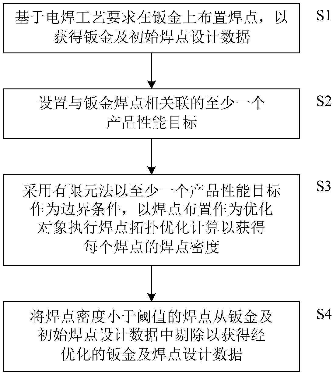
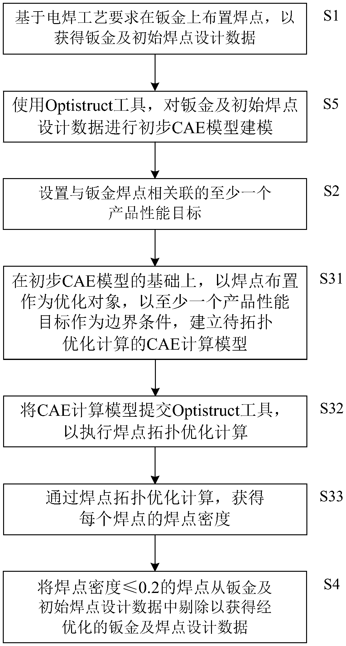
[0007] In order to solve the technical problems that it is difficult to determine the reasonable position and number of solder joints in the existing traditional solder joint design method, and the later verification is time-consuming and laborious, and to reduce the dependence on the experience of designers and effectively reduce the development cycle of the whole vehicle, the present invention provides A solder joint design method is provided for determining the solder joint layout on a sheet metal, the above solder joint design method may include:

Method used


Image

  • Welding spot design method and device
  • Welding spot design method and device
  • Welding spot design method and device

Examples


Embodiment Construction

[0065] The implementation of the present invention will be illustrated by specific specific examples below, and those skilled in the art can easily understand other advantages and effects of the present invention from the content disclosed in this specification. Although the description of the invention will be presented in conjunction with a preferred embodiment, it is not intended that the features of the invention be limited to that embodiment only. On the contrary, the purpose of introducing the invention in conjunction with the embodiments is to cover other options or modifications that may be extended based on the claims of the present invention. The following description contains numerous specific details in order to provide a thorough understanding of the present invention. The invention may also be practiced without these details. Also, some specific details will be omitted from the description in order to avoid obscuring or obscuring the gist of the present inventio...


PUM


Abstract

The invention belongs to the technical field of whole vehicle welding, and particularly discloses a welding spot design method and device. The design method can comprise the following steps of: arranging welding spots on a metal plate based on an electric welding process requirement to obtain the metal plate and initial welding spot design data; setting at least one product performance target associated with the sheet metal welding spot; adopting a finite element method to take at least one product performance target as a boundary condition, taking the welding spot arrangement as an optimization object to execute welding spot topological optimization calculation to obtain the welding spot density of each welding spot, and indicating the importance degree of the corresponding welding spot to reach the at least one product performance target by the welding spot density; and removing the welding spots with the welding spot density smaller than a threshold value from the metal plate and the initial welding spot design data to obtain optimized metal plate and welding spot design data. The problems that reasonable welding spot positions and welding spot number are difficult to determineand time and labor are wasted in later verification can be solved, experience dependence on designers can be reduced to a great extent, and the development period of the whole vehicle is effectively shortened.

Description

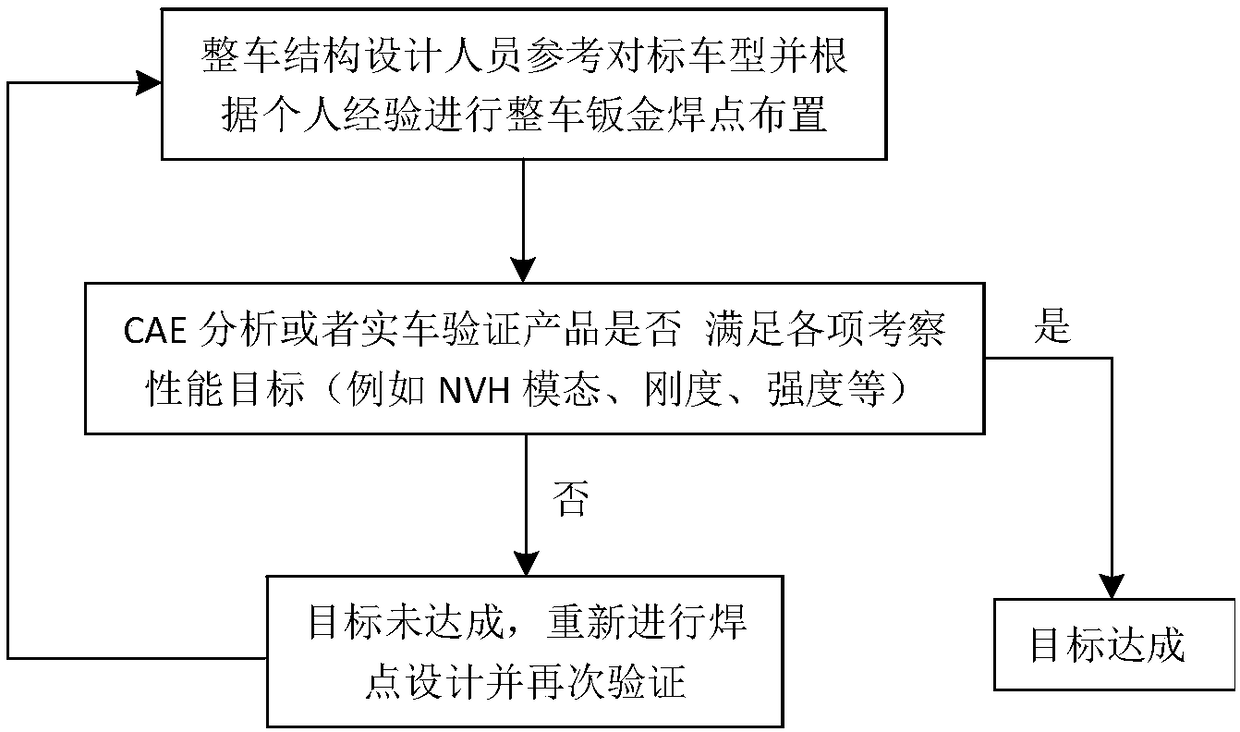
technical field [0001] The invention relates to the field of vehicle welding technology, in particular to a welding point design method and a welding point design device. Background technique [0002] The spot welding connection method has the advantages of high process efficiency and easy automation. At present, it is widely used in the production of automobile body-in-white, accounting for more than 70% of all connection methods of the entire vehicle. [0003] In the existing automobile design, the layout of sheet metal solder joints mainly includes two parameters, the position of the solder joints and the number of solder joints, which are often carried out by reference to the benchmarking vehicle. Since there are often many structural inconsistencies between the design model and the benchmarking car, the layout of solder joints cannot all refer to the benchmarking car. In order to meet the various performance target values ​​(such as NVH modal, stiffness, strength, etc....

Claims


Application Information

Patent Timeline
Patent Type & Authority Applications(China)
IPC IPC(8): G06F17/50
CPCG06F30/15G06F30/20
Inventor 万守臣
Owner WM SMART MOBILITY (SHANGHAI) CO LTD
Learn More