
Three-position spring operating mechanism

An operating mechanism and three-station technology, applied in the direction of contact drive mechanism, grounding device, electrical components, etc., can solve the problems of cumbersome linkage steps and multiple failure points, so as to improve linkage procedures, reduce failure points, and reduce misoperation The effect of probability

Active Publication Date: 2019-03-19
浙江博为电气有限公司
View PDF8 Cites 0 Cited by
  • Summary
  • Abstract
  • Description
  • Claims
  • Application Information

AI Technical Summary

Problems solved by technology

[0003] Most of the existing three-station operating mechanisms use multiple sets of independent components to block each operating hole, so cumbersome linkage steps are required between each set of interlocking devices, so there will be more failure points

Method used


Image

  • Three-position spring operating mechanism
  • Three-position spring operating mechanism
  • Three-position spring operating mechanism

Examples


Embodiment Construction

[0033] The following will clearly and completely describe the technical solutions in the embodiments of the present invention with reference to the accompanying drawings in the embodiments of the present invention. Obviously, the described embodiments are only part of the embodiments of the present invention, not all of them. Based on the embodiments of the present invention, all other embodiments obtained by persons of ordinary skill in the art without creative efforts fall within the protection scope of the present invention.

[0034] It should be noted that all directional indications (such as up, down, left, right, front, back...) in the embodiments of the present invention are only used to explain the relationship between the components in a certain posture (as shown in the accompanying drawings). Relative positional relationship, movement conditions, etc., if the specific posture changes, the directional indication will also change accordingly.

[0035] In the present in...


PUM


Abstract

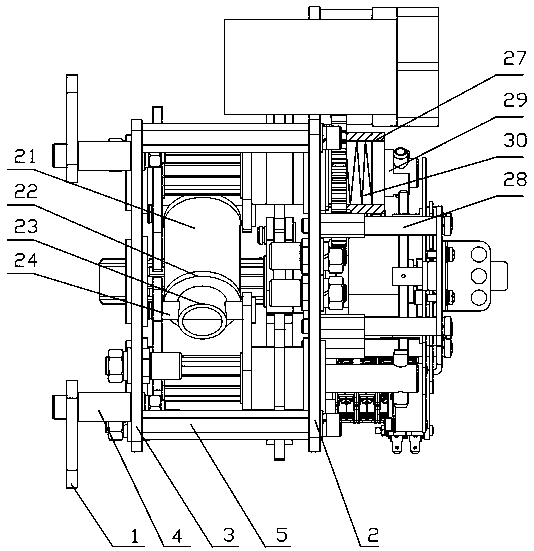
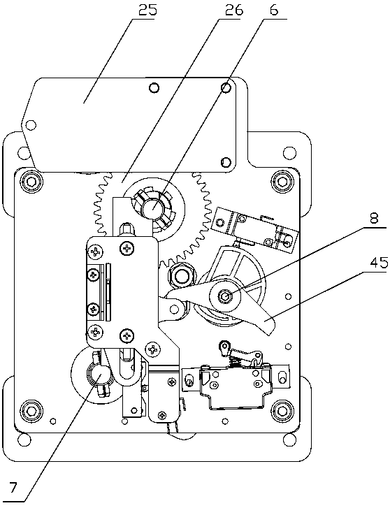
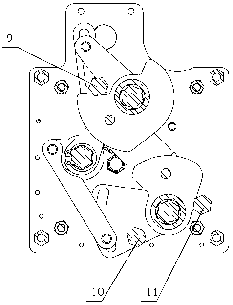
The invention discloses a three-position spring operating mechanism which comprises symmetrically disposed front and rear clamping plates between which an energy storage control mechanism is fixedly installed. An interlocking mechanism is arranged on the other side of the front clamping plate. The interlocking mechanism comprises an operation interlocking mounting plate fixedly disposed on the front clamping plate; an operation hole locking plate slidably arranged on the operation interlocking mounting plate; a guiding mechanism; a closing and opening position locking plate; a main knife operating shaft and a ground knife operating shaft disposed at the upper and lower ends of the guiding mechanism. The guiding mechanism has a first position that is driven by a closing and opening positionshift fork to be in stopping engagement with the stopping portion of the main knife operating shaft and a second position to be in stopping engagement with the stopping portion of the ground knife operating shaft, thereby achieving an effect that one interlocking component realizes reliable interlock between the main knife operation hole and the ground knife operation hole, ensuring the logical operation sequence of the mechanism, improving the disadvantages that a plurality of independent components lock the operation holes in the past, improving the complicated linkage program between multiple components, reducing many fault point, making the interlocking device more concise and reliable than a previous interlocking device, achieving simpler and clear operation, reducing a misoperationprobability, achieving good practicality.

Description

technical field [0001] The invention relates to the technical field of electric equipment, in particular to a three-position spring operating mechanism. Background technique [0002] The three-station operating mechanism is widely used in the high-voltage ring network cabinet, and cooperates with the circuit breaker to switch on and off the main circuit. The current three-position operating mechanism is mainly driven by the main shaft to realize the closing, opening and grounding operations of the circuit breaker, and the interlocking device of the three-position switch operating mechanism is an important part of the switch operating mechanism to prevent misoperation. As well as improving the protection level of the mechanism room, its reliability and stability play a vital role in the normal operation of the switchgear and the safety of the staff. [0003] However, most of the existing three-station operating mechanisms use multiple sets of independent components to block ...

Claims


Application Information

Patent Timeline
Patent Type & Authority Applications(China)
IPC IPC(8): H01H3/46H02B1/16H02B1/32
Inventor 黄余良陈庆楷
Owner 浙江博为电气有限公司
Learn More