Coining die for outer strip of nuclear fuel assembly positioning grid frame

A technology for nuclear fuel assemblies and spacer grids, which is used in manufacturing tools, forming tools, metal processing equipment, etc., and can solve problems such as the processing technology of strips without spacer grids.

Inactive Publication Date: 2019-03-22
CHINA NUCLEAR BAOTOU GUANGHUA CHEM IND
View PDF5 Cites 9 Cited by
  • Summary
  • Abstract
  • Description
  • Claims
  • Application Information

AI Technical Summary

Problems solved by technology

At present, there is no processing technology for the strips outside the positioning grid

Method used


Image

  • Coining die for outer strip of nuclear fuel assembly positioning grid frame
  • Coining die for outer strip of nuclear fuel assembly positioning grid frame
  • Coining die for outer strip of nuclear fuel assembly positioning grid frame

Examples


Embodiment Construction

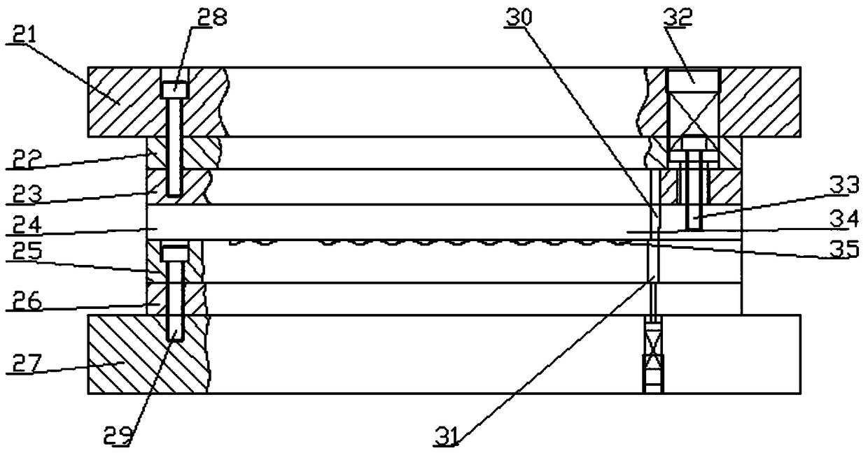
[0024] A stamping mold for the outer band of the nuclear fuel component positioning grid, including a stamping mold for the overall shape, a bending and chamfering mold for the end of the outer strip, a right-angle bending mold, and a lapping bending mold;

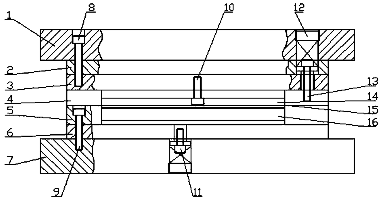
[0025] figure 1 Shown is the structure diagram of the stamping die for the overall shape of the outer strip. The stamping die for the overall shape includes the upper die base A1, the upper die backing plate A2, and the upper die plate A3. The upper die base A1, the upper die backing plate A2, and the upper die plate A3 pass through The bolt AA8 is connected, the upper formwork A3 and the unloading plate A4 are connected by the bolt AC10, the limit column A13 is located in the holes corresponding to the upper formwork backing plate A2, the upper formwork A3 and the unloading plate A4, and the plug screw A12 is located in the upper die base A1 The upper and lower formwork A5, the lower mold backing plate A6, and the lower m...


PUM


Abstract

The invention discloses a single-station die applied to the machining of an outer strip of a fuel assembly positioning grid frame. The single-station die applied to the machining of the outer strip ofthe fuel assembly positioning grid frame aims to meet the machining mode of the outer strip of the fuel assembly positioning grid frame and enable the outer strip of the positioning grid frame to meet the drawing and technical requirements, so that the smooth production of products is ensured. An overall shape punching die, an outer strip end bending and chamfering die and a right-angle bending and overlapping bending die are included.

Description

technical field [0001] The invention belongs to the technical field of nuclear fuel components, and in particular relates to a punching mold for strips outside a positioning grid of a nuclear fuel component. Background technique [0002] The outer strip of the nuclear fuel assembly positioning grid is a sheet-shaped thin-walled metal structure. There are several protective wing shapes at the upper and lower ends of the strip, which are symmetrically and evenly distributed. The middle section of the strip has a 90° bending structure at one end. There are overlapping raised structures. This type of strip metal stamping process requires very high precision and should be able to meet large-scale stamping according to production needs. At present, there is no processing technology for the strips outside the positioning grid. Based on the above reasons, a special stamping die is designed to solve this problem. Contents of the invention [0003] The purpose of the invention is...

Claims


Application Information

Patent Timeline
Patent Type & Authority Applications(China)
IPC IPC(8): B21D37/10
Inventor 李健伟韩璐乔玉祥王耀华齐志峰吴鹏侯伟宁王慧敏
Owner CHINA NUCLEAR BAOTOU GUANGHUA CHEM IND
Why Eureka
Try Eureka