An automatic steel wire brush machine

A brush machine and automatic manufacturing technology, which is applied in the direction of manufacturing tools, feeding devices, positioning devices, etc., can solve the problems of life-threatening, high labor costs, and easy to be injured, and achieve the reduction of steel wire material loss, reasonable structural design, and guaranteed use. safe effect

Active Publication Date: 2020-07-10
永康市航海涂附磨具厂
View PDF6 Cites 0 Cited by
  • Summary
  • Abstract
  • Description
  • Claims
  • Application Information

AI Technical Summary

Problems solved by technology

[0002] The steel wire brush made by the old technology is manually cut off the steel wire, and the steel wire is pressed into the brush cap by manual operation, and the steel wire is pressed into the brush cap by manual cutting. The production process is not only high in labor costs, but also low in efficiency. The main punching machine has potential safety hazards, and workers are easily injured if they operate improperly. The steel wire brush on the lock of the punching machine is a hexagonal lock. The steel wire inside the brush is easy to fall off and fly out, and the hexagonal locking process of the brush directly affects the product quality and service life of the product, and the most terrible thing is that it is prone to personal safety accidents or life-threatening

Method used


Image

  • An automatic steel wire brush machine
  • An automatic steel wire brush machine
  • An automatic steel wire brush machine

Examples


Embodiment Construction

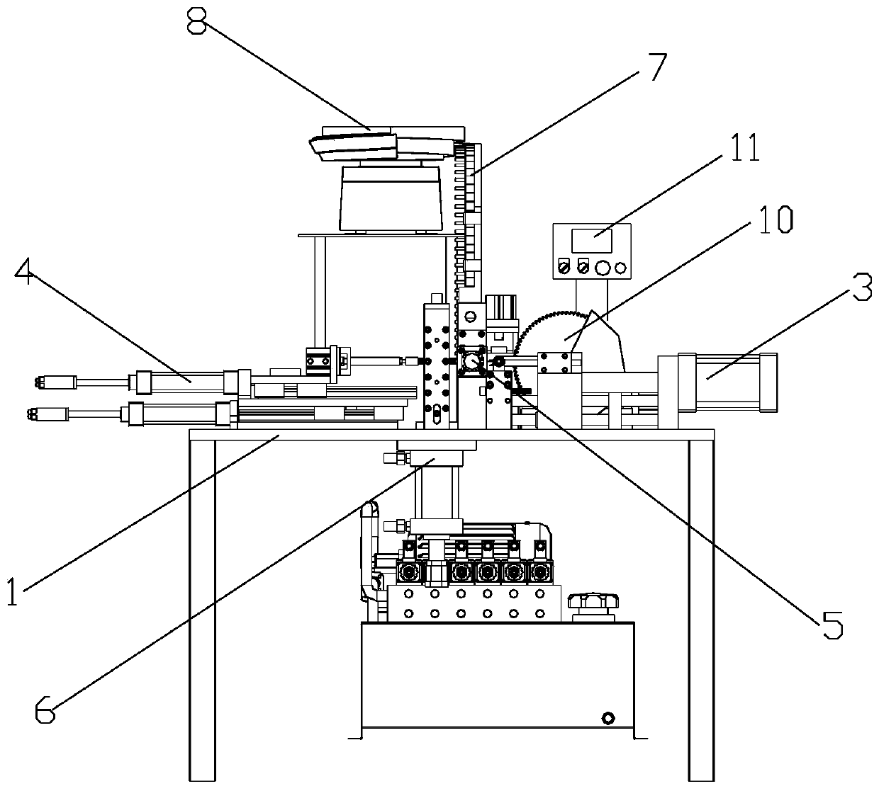
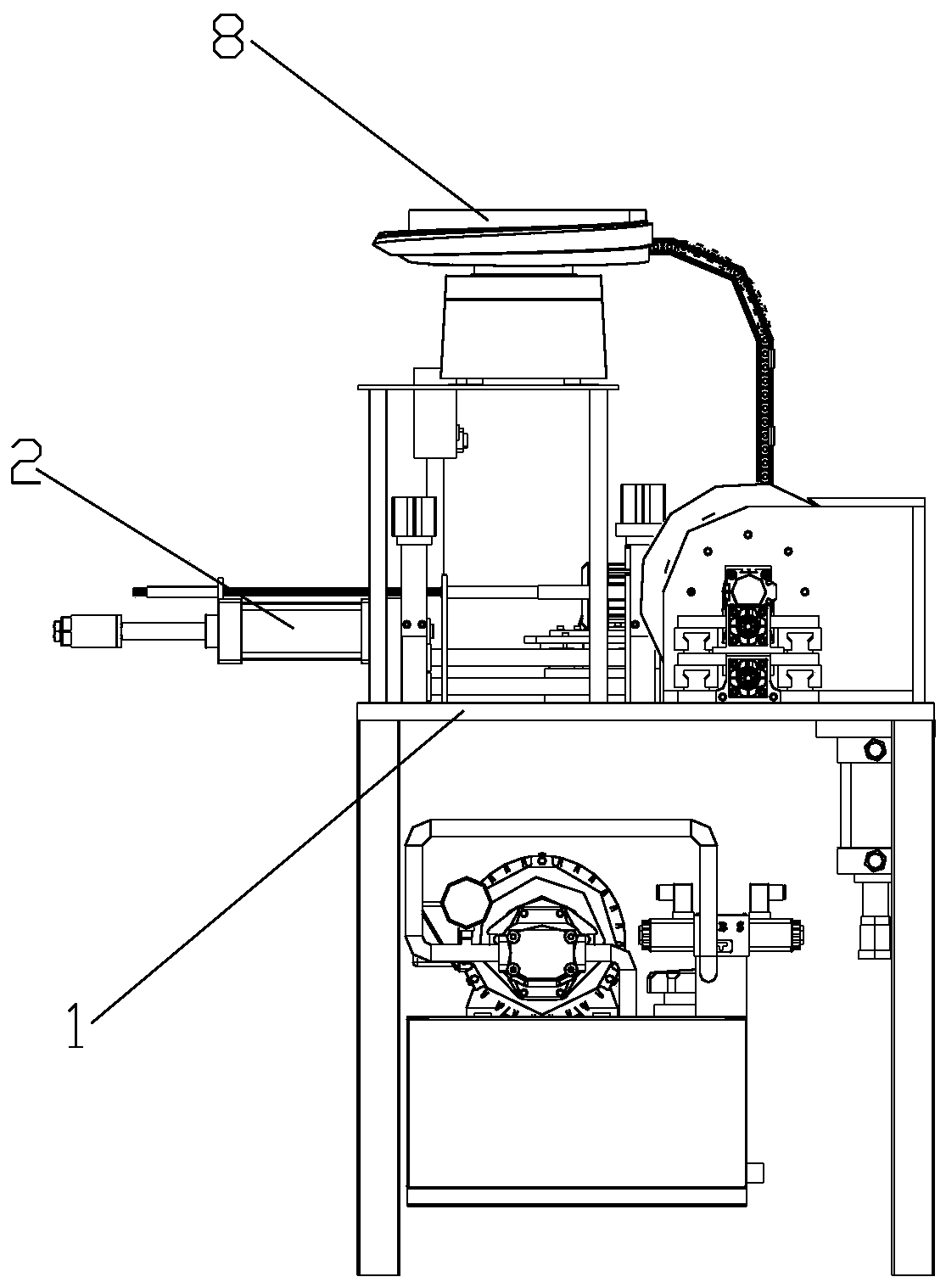
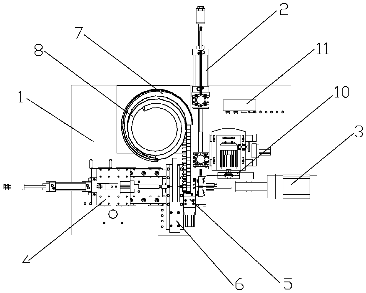
[0028] Such as Figure 1-Figure 15 As shown, the specific embodiment adopts the following technical scheme: it includes a workbench 1, a steel wire entering device 2, a pushing steel wire pressing device 3, a manipulator 4, a brush cap feeding auxiliary wire feeding mechanism 5, a locking mechanism 6, and a track 7 , vibrating plate 8, bracket 9, wire cutting mechanism 10, controller 11, steel wire entering device 2, pushing steel wire pressing device 3 and manipulator 4 are installed on the table of workbench 1, between pushing steel wire pressing device 3 and manipulator 4 A brush cap feeding auxiliary wire feeding mechanism 5 and a locking mechanism 6 are installed between them. A track 7 is installed on the brush cap feeding auxiliary wire feeding mechanism 5. One end of the rail 7 is wound on the vibrating disc 8, and the vibrating disc 8 passes through the bracket 9. Fixed on the workbench 1, the wire cutting mechanism 10 is set on the workbench 1 through the wire cuttin...


PUM


Abstract

The invention discloses an automatic steel wire pen brush making machine, and relates to the field of pen brush machines. A steel wire inlet device, a steel wire pushing and pressing device and a mechanical hand are mounted on the table board of a working table; a brush cap feeding auxiliary wire inlet mechanism and a lock hole mechanism are mounted between the steel wire pushing and pressing device and the mechanical hand; a rail is mounted on the brush cap feeding auxiliary wire inlet mechanism; one end of the rail is wound on a vibrating disc; the vibrating disc is fixedly arranged on the working table through a bracket; a wire cutting mechanism is mounted on the steel wire pushing and pressing device; and a controller is mounted on the working table. An existing hexagonal reducing device is changed to be an octagonal reducing device, and a hydraulic octagonal process product is tighter in wire bundling; during high-speed rotation use, steel wires inside the pen brush can achieve 100% no-drop flying wires and guarantee use safety, so that concentricity is stable, hands are not vibrated, the service life of the steel wire pen brush is prolonged, working efficiency, which is at least improved by 8 times or more in compassion with that of a manual punch reducing way, of the steel wire pen brush is improved, and labour cost is greatly reduced.

Description

Technical field: [0001] The invention relates to an automatic steel wire brush machine, which belongs to the technical field of steel wire brush machines. Background technique: [0002] The steel wire brush made by the old technology is manually cut the steel wire, and the steel wire is pressed into the brush cap by manual operation, and the steel wire is pressed into the brush cap by manual cutting. The production process is not only high in labor costs, but also low in efficiency. The main punching machine has potential safety hazards, and workers are easily injured if they operate improperly. The steel wire inside the brush is easy to fall off and fly out, and the hexagonal locking process of the brush directly affects the product quality and service life of the product, and the most terrible thing is that it is prone to personal safety accidents or life-threatening. Invention content: [0003] In view of the above problems, the technical problem to be solved by the pr...

Claims


Application Information

Patent Timeline
Patent Type & Authority Patents(China)
IPC IPC(8): B21D39/00B21F11/00B21D43/10B21F23/00
CPCB21D39/00B21D43/105B21F11/00B21F23/00
Inventor 应根华王园心
Owner 永康市航海涂附磨具厂
Why Eureka
Try Eureka