Automatic centering chuck

A centering chuck, automatic technology, applied in the direction of the chuck, etc., can solve the problems of long time spent, complicated calibration process, difficult to guarantee the accuracy, etc., to prolong the service life, facilitate disassembly and maintenance and cleaning, and improve the stability Effect

Active Publication Date: 2019-03-22
QUICK ROBOT TECH SHANGHAICO
View PDF14 Cites 19 Cited by
  • Summary
  • Abstract
  • Description
  • Claims
  • Application Information

AI Technical Summary

Problems solved by technology

[0002] At present, after the common chuck clamps the workpiece, the calibration process is complicated, takes a long time, and the accuracy is difficult to guarantee. Although the hydraulic automatic centering chucks sold on the market can also achieve the purpose of fast clamping and automatic centering, But the price is expensive, and there is an urgent need for a self-centering chuck with excellent performance and a reasonable price to meet market demand.

Method used


Image

  • Automatic centering chuck
  • Automatic centering chuck
  • Automatic centering chuck

Examples


Embodiment Construction

[0018] The present invention will be described in further detail below in conjunction with the accompanying drawings and embodiments. Wherein the same components are denoted by the same reference numerals. It should be noted that the words "front", "rear", "left", "right", "upper" and "lower" used in the following description refer to the directions in the drawings, and the words "bottom" and "top "Face", "inner" and "outer" refer to directions toward or away from, respectively, the geometric center of a particular component.

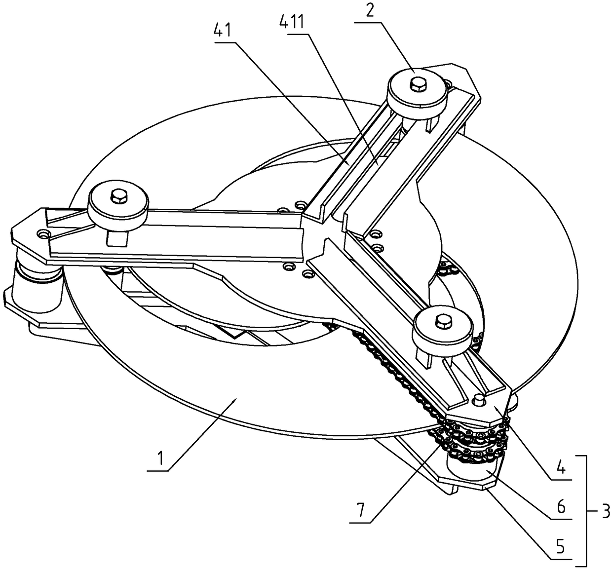
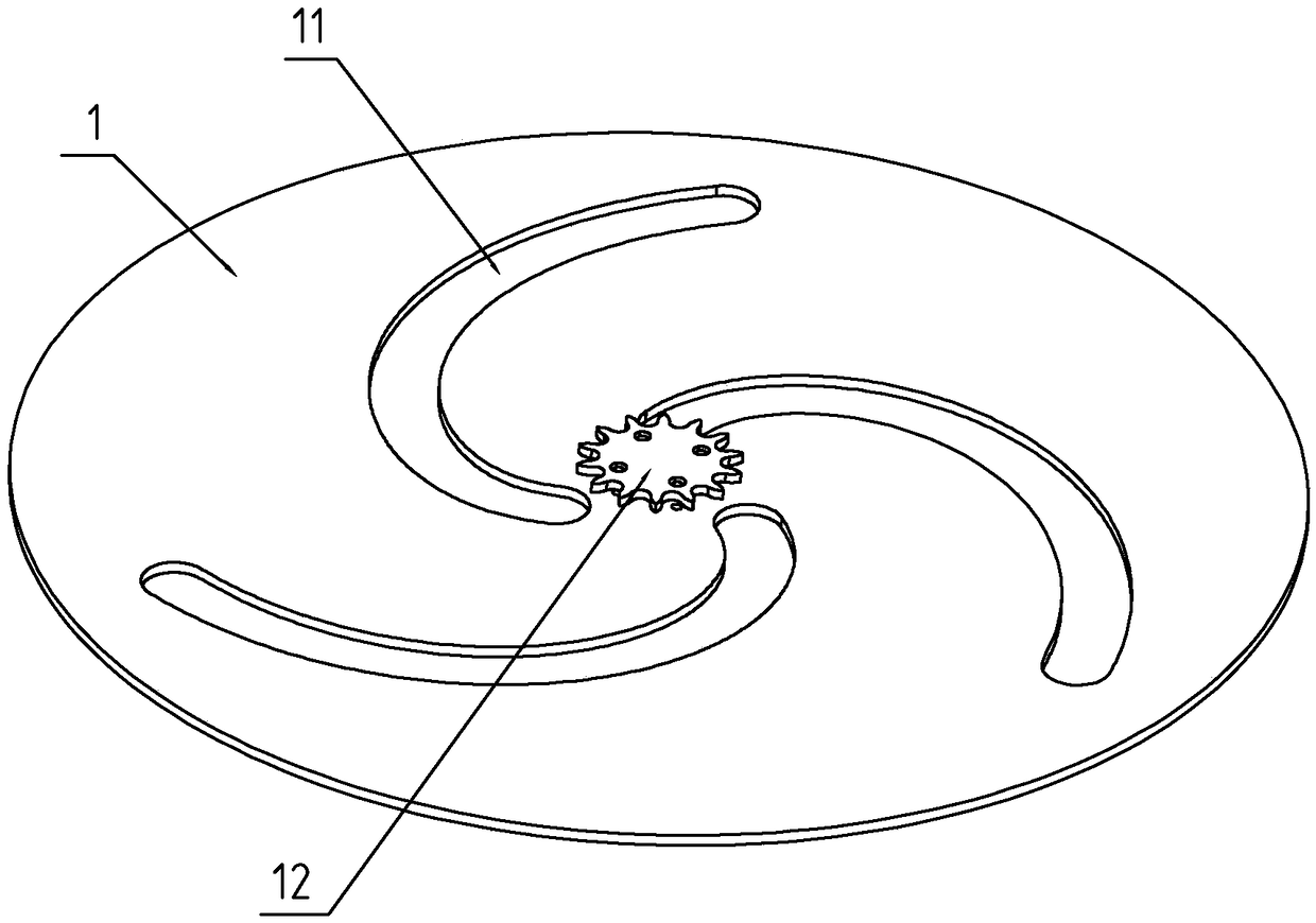
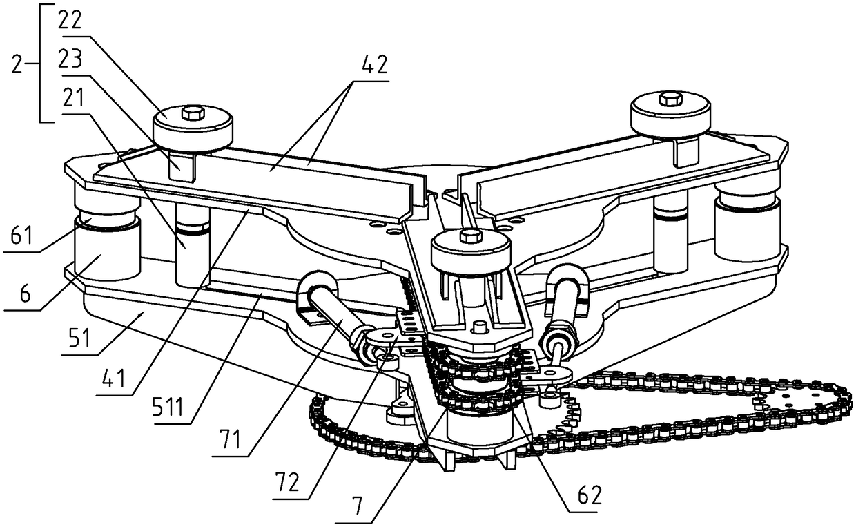
[0019] refer to Figure 1-5 As shown, a self-centering chuck includes a chuck body 1 and a plurality of jaws 2 slidingly connected to the chuck body 1. The chuck body 1 is arranged in a disc-shaped structure, and the chuck body 1 is arranged There is a first chute 11 for directional sliding of the claw 2, the claw 2 can slide along the length direction of the first chute 11, and the claw 2 includes a rotating rod 21 penetrating through the first chute...


PUM


Abstract

The invention discloses an automatic centering chuck with excellent performance and simple structure. According to the technical scheme, the automatic centering chuck is characterized in that the automatic centering chuck comprises a chuck body and a plurality of claws; a first chute is formed on the chuck body; the claws include rotating rods and abutting wheels; the first chute is arranged spirally; the distance dimension from the center of the chuck body to the first chute is gradually shortened along the length direction of the first chute; the chuck body rotates in the circumferential direction and is connected with a driving device; the driving device includes an upper bracket, a lower bracket and a support rod; the upper bracket includes an upper sliding arm; the lower bracket includes a lower sliding arm; the support rod is fixedly connected to the ends between the upper sliding arm and the lower sliding arm in a support mode; a rotating wheel is connected with the support rodin a rotating mode; the upper sliding arm is provided with a second chute; the lower sliding arm is provided with a third chute; and the upper bracket and the lower bracket can push rotating rods to slide along the length of the first chute, the second chute and the third chute during synchronous rotation so as to be close to or away from the center of the chuck body.

Description

technical field [0001] The present invention relates to a clamping device, more specifically, it relates to a self-centering chuck. Background technique [0002] At present, after the common chuck clamps the workpiece, the calibration process is complicated, takes a long time, and the accuracy is difficult to guarantee. Although the hydraulic automatic centering chucks sold on the market can also achieve the purpose of fast clamping and automatic centering, However, the price is expensive, and there is an urgent need for a self-centering chuck with excellent performance and a reasonable price to meet market demand. Contents of the invention [0003] Aiming at the deficiencies in the prior art, the purpose of the present invention is to provide a self-centering chuck with excellent performance and simple structure. [0004] In order to achieve the above object, the present invention provides the following technical solutions: a self-centering chuck, including a chuck body ...

Claims


Application Information

Patent Timeline
Patent Type & Authority Applications(China)
IPC IPC(8): B23B31/103
CPCB23B31/103
Inventor 金新元李家华何涛梁之栋
Owner QUICK ROBOT TECH SHANGHAICO
Why Eureka
Try Eureka