Cutting chamfering machine

A chamfering machine and chamfering technology, which is applied to the parts of grinding machine tools, machine tools suitable for grinding workpiece edges, stone processing equipment, etc. problem, to prevent cracking and reduce the effect of cracking

Pending Publication Date: 2019-03-22
FOSHAN YONGSHENGDA MACHINERY
View PDF0 Cites 3 Cited by
  • Summary
  • Abstract
  • Description
  • Claims
  • Application Information

AI Technical Summary

Problems solved by technology

Since the two processes are separated and carried out on different machines, the efficiency is low. Moreover, due to the large number of handling times, it is easy to damage the cut tiles or stones during the handling process.
In addition, the slitting of ceramic tiles or stones in the prior art is completed by a cutting knife. When a certain cutting speed needs to be guaranteed, the cutting blade needs to have a certain force to act on the tiles or stones. When the force is greater than the connecting force of the cut marks connecting the tiles on both sides, the cut marks will crack. Since the cutting blade is circular, when the cutting knife cuts to the end of the tile or stone, the cut marks are angular. At this time, the The cut is the easiest to crack, and after the crack, the angular crack will form an irregular cut edge that does not meet the requirements

Method used


Image

  • Cutting chamfering machine
  • Cutting chamfering machine

Examples


Embodiment Construction

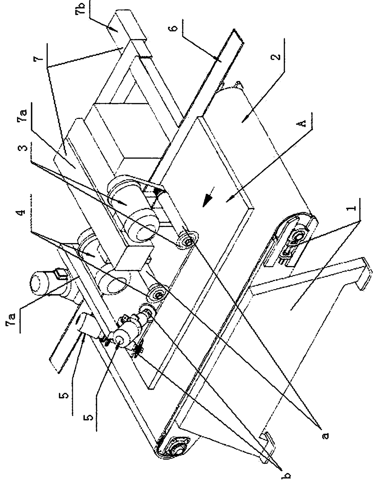
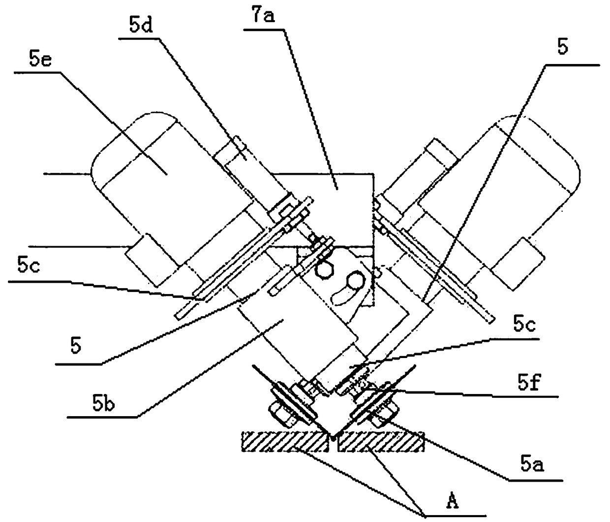
[0010] Now in conjunction with accompanying drawing and embodiment the present invention is described in further detail:

[0011] Such as figure 1 , 2 As shown, the present invention includes a frame 1, a transmission mechanism 2 arranged on the frame 1, a slitting mechanism a, a chamfering processing mechanism b, a slitting mechanism located on the transmission mechanism 2 and sequentially arranged on the frame 1. a by the front power cutting cutter head 3 (comprising the cutter head that is arranged on the frame by rotating the rotating shaft, the driven pulley connected on the rotating shaft, the motor arranged on the frame, the driving pulley connected on the motor rotating shaft, connected on the The belt between the driving pulley and the driven pulley), the rear power slitting cutterhead 4 (including the cutterhead that is arranged on the frame by rotating the rotating shaft, the driven pulley connected on the rotating shaft, the motor that is arranged on the frame, an...


PUM


Abstract

The invention relates to a cutting chamfering machine. The cutting chamfering machine is characterized by comprising a rack, a transmission mechanism, a splitting mechanism and a chamfering mechanism;and the transmission mechanism is arranged on the rack, the splitting mechanism and the chamfering mechanism are located on the transmission mechanism and are arranged on the rack in sequence from front to back, the splitting mechanism is formed by a front power splitting cutter disc and a back power splitting cutter disc, the chamfering mechanism comprises two power grinding discs which are arranged in sequence in the transmission direction of the transmission mechanism, the two power grinding discs are inclined to the transmission surface of the transmission mechanism, and the inclined directions of the two power grinding discs are opposite. Compared with the prior art, the cutting chamfering machine has the advantages that movement is not needed, ceramic tiles or stones can be chamfered on the same machine after being split, and cracking can be reduced and even prevented in the condition that the processing speed is not influenced.

Description

Technical field: [0001] The invention relates to a ceramic / stone processing technology. Background technique: [0002] After the existing stone or tiles are cut, chamfering processing is often required. The existing technology is carried out on two machines, one of which cuts the tiles or stones, and then sends the cut tiles or stones to Go to the chamfering machine for chamfering. Because the two processes are separated and carried out on different machines, the efficiency is low, and, due to the large number of times of handling, it is easy to damage the cut tiles or stone materials during the handling process. In addition, the slitting of ceramic tiles or stones in the prior art is completed by a cutting knife. When a certain cutting speed needs to be guaranteed, the cutting blade needs to have a certain force to act on the tiles or stones. When the force is greater than the connecting force of the cut marks connecting the tiles on both sides, the cut marks will crack. ...

Claims


Application Information

Patent Timeline
Patent Type & Authority Applications(China)
IPC IPC(8): B24B9/06B24B27/00B24B41/00B28D1/00B28D1/24B28D7/04
CPCB24B9/06B24B27/0023B24B27/0069B24B27/0076B24B41/005B28D1/003B28D1/24B28D7/04
Inventor 刘永钦
Owner FOSHAN YONGSHENGDA MACHINERY
Why Eureka
Try Eureka