
Motion floating mechanism

A technology of floating mechanism and row position, which is applied in the field of injection molds, can solve the problems that large-scale molding machines are not convenient for workers to operate, reduce the space utilization rate of the production workshop, and increase the stroke of the core-pulling structure, so as to optimize the product ejection structure and improve Effect of space utilization and reduction of mold length

Inactive Publication Date: 2019-03-22
中山市利群精密实业有限公司
View PDF2 Cites 0 Cited by
  • Summary
  • Abstract
  • Description
  • Claims
  • Application Information

AI Technical Summary

Problems solved by technology

[0003] When the inner wall of the injection molded product has a semi-closed groove or a through-hole groove, and the outer wall has structures such as undercuts, buckles, and bosses, the product is generally pushed out through the thimble when the outer wall structure is separated from the rear mold core, but the thimble is used to push the product out. When the product is pushed out, the surface of the product is easy to appear white, and there are marks on the thimble, which increases the defective rate of the product; if the product structure is more complicated, the product cannot be ejected through the thimble; and the semi-closed groove or through hole of the injection molded product The groove structure cannot be directly removed from the mold, and the injection molding and demoulding process of the injection molded product needs to be completed by means of a core pulling mechanism
[0004] However, when the product has a long-hole structure in the market, when designing a long-hole mold, the core-pulling mechanism is usually set on the side of the mold, and then the movable core is controlled by the oil cylinder to separate it from the product. When the core-pulling structure is too high, the movable core of the core-pulling structure must be completely separated from the product to take out the product, then the stroke of the core-pulling structure will increase, and the length of the oil cylinder will be longer. When the designed mold length is longer, a relatively large mold is required. The molding machine can complete the production of the product
Regardless of whether it is a large or small enterprise, large molding machines not only occupy the space of the production workshop, reduce the space utilization rate of the production workshop, and greatly increase the cost burden, but also usually require multiple molding machines to produce products. To meet the production demand, large molding machines cannot meet the placement demand, thus unable to meet the production demand
Furthermore, large molding machines are inconvenient for workers to operate and extremely inconvenient to maintain

Method used


Image

  • Motion floating mechanism
  • Motion floating mechanism
  • Motion floating mechanism

Examples


Embodiment Construction

[0020] In order to make the technical problems, technical solutions and advantages to be solved by the present invention clearer, the following will describe in detail with reference to the drawings and specific embodiments.

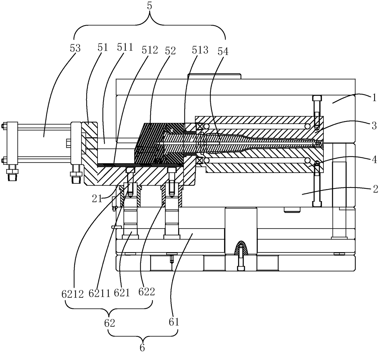
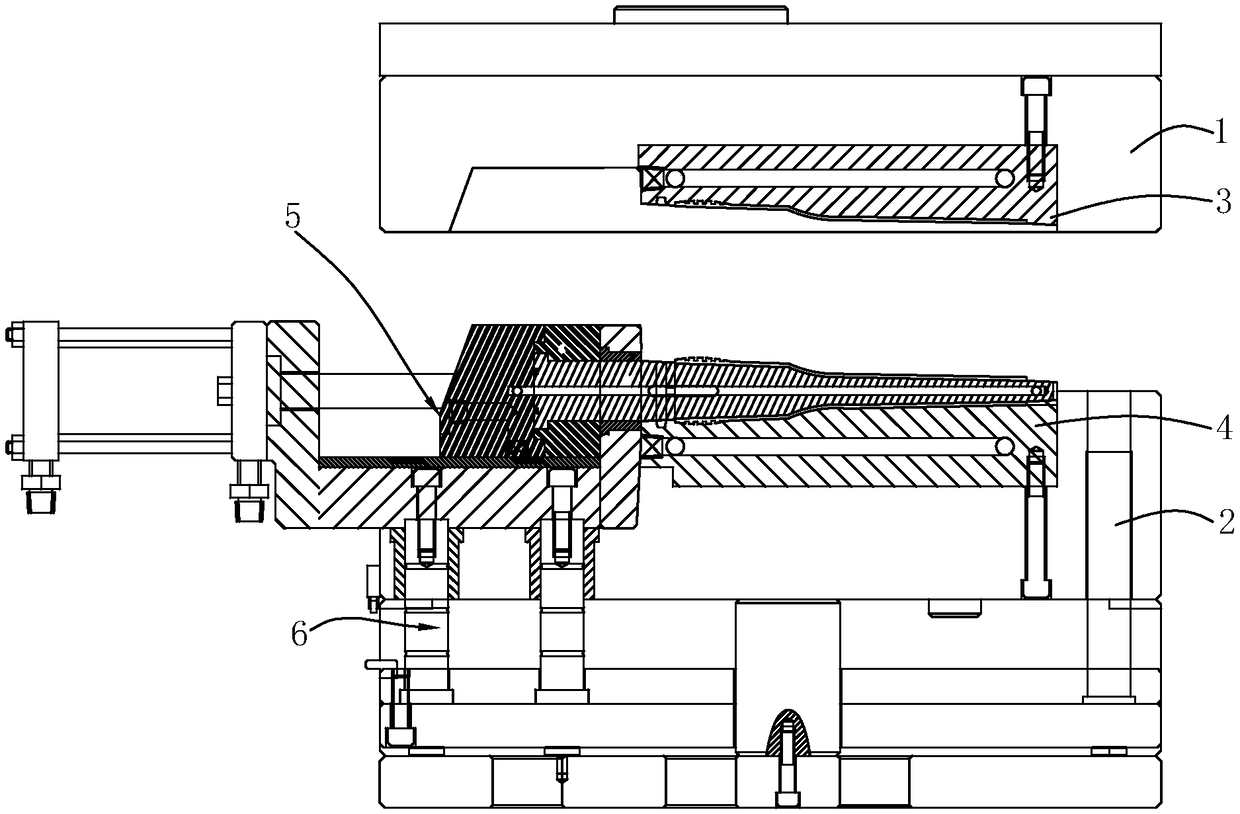
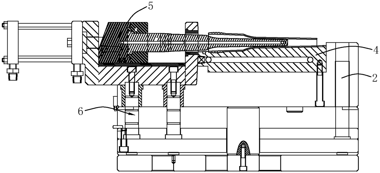
[0021] Such as figure 1 As shown, the row position floating mechanism of the present invention comprises a front mold 1 and a back mold 2, a front mold cavity 3 is provided on the side of the front mold 1 facing the back mold 2, and a front mold cavity 3 is provided on the back mold 2. Cooperating rear mold core 4 is provided with a fixed groove 21 on the side of the rear mold 2 near the rear mold core 4, and is provided with a core-pulling mechanism 5 that can complete the core-pulling of the mold cavity on the fixed groove 21. The lower part is provided with a pusher device 6 that pushes the core pulling mechanism 5 toward the front mold 1 . refer to Figure 2 to Figure 4 After the front mold 1 and the rear mold 2 are opened, the core-pulling mechani...


PUM


Abstract

The invention relates to a motion floating mechanism which comprises a front mold and a rear mold. A front mold cavity is formed in the side, right facing the rear mold, of the front mold. A rear moldcore matched with the front mold cavity is arranged on the rear mold. A fixed groove is formed in the side, close to the rear mold core, of the rear mold. A core pulling mechanism capable of completing mold cavity core pulling is arranged on the fixed groove. A part pushing device for pushing the core pulling mechanism towards the front mold is arranged on the lower portion of the core pulling mechanism. According to the motion floating mechanism, the problems that when products are ejected out, the surfaces are white, marks are left, the structures of the product outer walls are complex, andconsequently the products cannot be ejected out through ejector pins are solved; and meanwhile, the motion stroke of the core pulling mechanism is reduced to a great degree, the mold length is reduced, the space utilization rate of enterprise production workshops is improved, and the production cost and the mold manufacturing cost are correspondingly reduced.

Description

technical field [0001] The invention relates to an injection mold, in particular to a row position floating mechanism. Background technique [0002] The injection mold consists of two parts, the movable mold and the fixed mold. The movable mold is installed on the movable template of the injection molding machine, and the fixed mold is installed on the fixed template of the injection molding machine. During injection molding, the movable mold and the fixed mold are closed to form a gating system and The cavity, when the mold is opened, the movable mold and the fixed mold are separated to take out the plastic product. [0003] When the inner wall of the injection molded product has a semi-closed groove or a through-hole groove, and the outer wall has structures such as undercuts, buckles, and bosses, the product is generally pushed out through the thimble when the outer wall structure is separated from the rear mold core, but the thimble is used to push the product out. When...

Claims


Application Information

Patent Timeline
IPC IPC(8): B29C45/33B29C45/40B29C45/44
CPCB29C45/33B29C45/4005B29C45/44B29C2045/445
Inventor 阮建华张建群张宇昂何可梅戴飞军
Owner 中山市利群精密实业有限公司
Learn More