Water resistance load adjustment device

A technology of load regulation and water resistance, used in power supply testing, motor generator testing, etc., can solve problems such as affecting the accuracy of electrical performance testing, complex motion adjustment mechanisms, and abrasion of wire insulation, achieving fully automatic control, improving Continuity, the effect of improving accuracy

Active Publication Date: 2021-08-10
DAYU ELECTRIC
View PDF11 Cites 0 Cited by
  • Summary
  • Abstract
  • Description
  • Claims
  • Application Information

AI Technical Summary

Problems solved by technology

[0003] The load power of the above-mentioned device is large, and the resistance value can be adjusted steplessly, but there are still some disadvantages in the actual test process: 1) the motion adjustment mechanism is relatively complicated, and the investment cost is high; 2) the cable connected to the pole plate It will move up and down with the plate, which will easily cause the insulation layer of the wire to wear, the cable connection to loosen or the cable to break, which will affect the accuracy of the electrical performance test; , The drop of the liquid level causes the resistance value of the resistance liquid to fluctuate, which affects the accuracy of the electrical performance test

Method used


Image

  • Water resistance load adjustment device
  • Water resistance load adjustment device

Examples


Embodiment 1

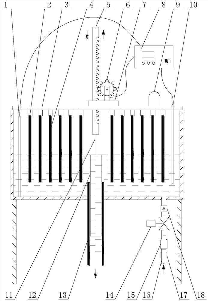
[0026] Embodiment 1: see figure 1 As shown, a water resistance load adjustment device includes a hollow water resistance box 3, the inside of the top plate of the water resistance box 3 is provided with a plurality of insulating fixing seats 2 for installing electrode plates 4, and the lower end of the electrode plates 4 is immersed in the water resistance the water in box 3. The bottom plate of the water resistance box 3 is provided with a drain pipe 13, and one end of the drain pipe 13 passes through the bottom plate and communicates with the cavity of the water resistance box 3. An overflow pipe 12 is sleeved inside the drain pipe 13 , and the outer wall at the bottom of the overflow pipe 12 is in movable and sealed connection with the inner wall at the top of the drain pipe 13 .

[0027] see figure 1 As shown, the outside of the top plate of the water resistance box 3 is provided with a lifting device, and the lifting end of the lifting device passes through the top plat...

Embodiment 2

[0029] Embodiment 2: on the basis of embodiment 1, refer to figure 1 As shown, the lifting device includes a transmission fixed seat 7 installed on the outside of the top plate of the water resistance box 3, a motor is installed on the transmission fixed seat 7, the output end of the motor is connected with the rack 5 through a gear 6, and the lower end of the rack 5 The movement passes through the transmission fixing seat 7 and is connected with the overflow pipe 12, and is used to drive the overflow pipe 12 to move up and down. The gear with self-locking function is connected with the rack drive, the upper and lower positions of the movable overflow pipe are changed, the water level of the water resistance box 3 is adjusted by controlling the height of the overflow pipe 12, and the water in the water resistance box 3 and the electrode plate are changed. 4, thereby changing the resistance value between the electrode plates 4 to meet the requirement of adjusting the power of t...

Embodiment 3

[0031] Embodiment 3: on the basis of embodiment 1, refer to figure 1 As shown, the adjustment device also includes an audible and visual alarm 9 and a temperature sensor 10 , the temperature sensor 10 is arranged in the water resistance box 3 , and the audible and visual alarm 9 and the temperature sensor 10 are electrically connected to the controller 8 respectively.

[0032] The temperature sensor 10 is used to detect the water temperature in the water resistance box 3, and transmits the detection signal to the controller 8, and the controller 8 automatically controls the opening of the regulating valve 14 according to the water temperature and preset temperature parameters. It can not only reduce the frequency of manual operation, realize fully automatic control, but also further improve the control stability and precision of the water resistance load. For example: the preset temperature is 70°C, and when the water temperature exceeds 70°C, the controller 8 appropriately ad...


PUM


Abstract

The invention discloses a water resistance load adjusting device, which comprises a hollow water resistance box, a drainpipe is arranged on the bottom plate of the water resistance box, an overflow pipe is set inside the drainpipe, the outer wall of the lower part of the overflow pipe and the inner wall of the upper part of the drainpipe Movable sealing connection, the outer side of the top plate of the water resistance box is provided with a transmission fixing seat, and a motor is installed on the transmission fixing seat. The output end of the motor is connected to the rack through a gear, and the lower end of the rack moves through the transmission fixing seat to connect with the overflow pipe. The adjustment device also includes a water inlet pipe, the outlet of the water inlet pipe communicates with the cavity of the water resistance box, the water inlet pipe is provided with a regulating valve, and the control end of the regulating valve is electrically connected to the controller. The gear with self-locking function is connected with the rack drive to simplify the adjustment structure of the existing load device, which not only makes it more convenient to adjust the resistance value of the water resistance, but also changes the water volume in the water resistance box, so that the adjustment range of the resistance value is greatly increased. increase, reducing the investment cost of the existing load resistance device.

Description

technical field [0001] The invention relates to the technical field of electrical equipment performance testing, in particular to a water resistance load adjusting device. Background technique [0002] When performing electrical performance tests on high-power generators or other high-power power supply equipment, it is necessary to provide a simulated load. At present, the liquid resistance load device is mainly used as the simulated load for testing. The liquid resistance load device basically adopts a mechanical transmission mode, and the purpose of adjusting the resistance value of the resistance liquid is achieved by changing the contact area between the electrode and the resistance liquid. [0003] The load power of the above-mentioned device is large, and the resistance value can be adjusted steplessly, but there are still some disadvantages in the actual test process: 1) the motion adjustment mechanism is relatively complicated, and the investment cost is high; 2) th...

Claims


Application Information

Patent Timeline
Patent Type & Authority Patents(China)
IPC IPC(8): G01R31/34G01R31/40
CPCG01R31/34G01R31/40
Inventor 刘文剑王怡华李国俊
Owner DAYU ELECTRIC
Why Eureka
Try Eureka