Supercharge Your Innovation With Domain-Expert AI Agents!

A ring winding machine

A winding machine and ring-shaped technology, which is applied in the field of ring winding machines, can solve problems such as the upward jump of the magnetic core, affecting the uniformity and quality of the winding of the magnetic core, so as to ensure uniformity, avoid manual pulling, and reduce dangerous effect

Active Publication Date: 2021-01-26
JIANGYIN SPARK ELECTRONICS TECH
View PDF11 Cites 0 Cited by
  • Summary
  • Abstract
  • Description
  • Claims
  • Application Information

AI Technical Summary

Problems solved by technology

[0003] The object of the present invention is to overcome the defects in the prior art and provide a ring winding machine which can prevent the magnetic core from bouncing upwards during the winding process and affect the winding uniformity and winding of the magnetic core. line quality problem

Method used


Image

  • A ring winding machine
  • A ring winding machine
  • A ring winding machine

Examples


Embodiment 1

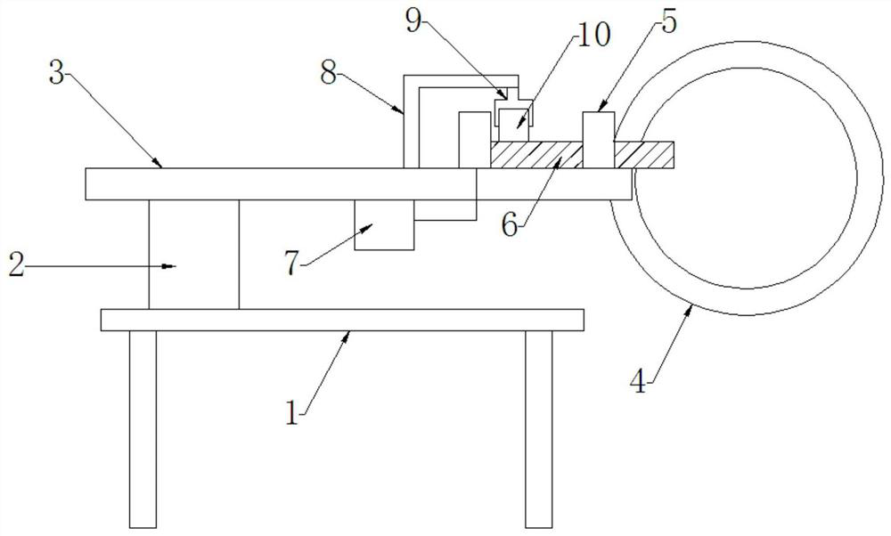
[0023] Such as Figure 1 to Figure 3 As shown, the present invention is a ring winding machine, including a frame, an assembly head, an electric control box, a transmission mechanism, a wire storage ring, and a magnetic core clamping mechanism. The magnetic core clamping mechanism includes a The support seat 2 on the frame 1, the support plate 3 horizontally arranged on the support seat, one end of the support plate is provided with a C-shaped groove, the central angle of the C-shaped groove is greater than 180 degrees; the wire storage ring 4 and the support plate The opening position of the C-shaped groove matches, and the plane of the support plate is perpendicular to the annulus of the wire storage ring; the support plate is evenly provided with at least three roller columns 5 perpendicular to the support plate and driven on the outer edge of the C-shaped groove. Roller, the roller column and the driving roller are provided with a roller and a driving wheel for clamping th...

Embodiment 2

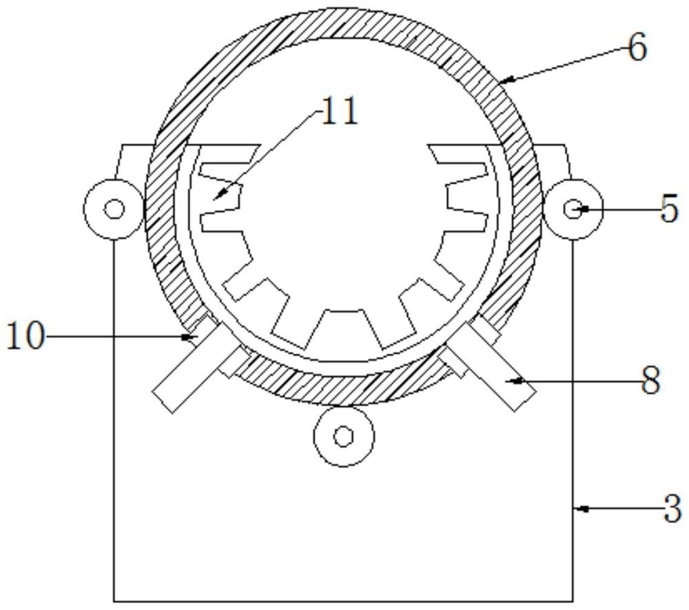
[0026] Such as Figure 4 As shown, the difference between Embodiment 2 and Embodiment 1 is that the magnetic core positioning component is a groove 15 provided on the support plate 3 for embedding the magnetic core, and the opening direction of the groove is C-shaped with the support plate. The opening directions of the grooves are consistent, and the bottom surface of the grooves is provided with notches 16 for accommodating rollers.

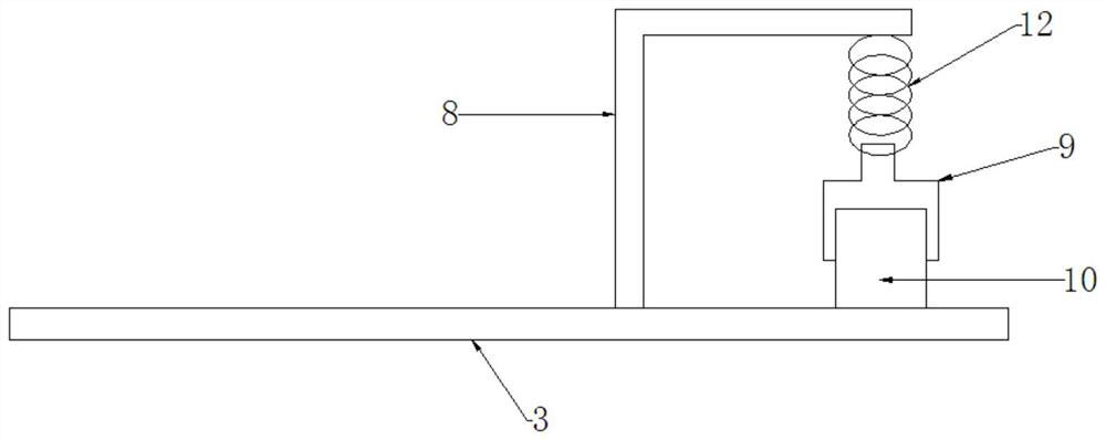
[0027] Such as Figure 5 As shown, the ring winding machine of the present invention also includes a wire fixing assembly, and the wire fixing assembly includes a fixing rod 13 arranged on the bottom surface of the support plate 3, and the end of the fixing rod is provided with a hook passing through the ring hole of the magnetic core 6 Bar 14, the hook bar is rotatably connected with the fixed bar.


PUM

PropertyMeasurementUnit
angleaaaaaaaaaa

Abstract

The invention discloses an annular winding machine, comprising a frame, an assembly head, an electric control box, a transmission mechanism, a wire storage ring, and a magnetic core clamping mechanism. A support seat and a support plate horizontally arranged on the support seat, one end of the support plate is provided with a C-shaped groove, and the central angle of the C-shaped groove is greater than 180 degrees; the opening position of the wire storage ring and the C-shaped groove of the support plate Matching, and the plane of the support plate is perpendicular to the annular surface of the wire storage ring; the support plate is evenly arranged on the outer edge of the C-shaped groove at least three roller columns and driving rollers perpendicular to the support plate, roller columns and driving rollers A roller and a driving wheel for clamping the magnetic core are arranged on the upper surface, and the driving wheel is connected with the transmission mechanism through the driving roller; and a magnetic core positioning assembly is also arranged on the support plate. In the present invention, the magnetic core positioning assembly is arranged on the support plate of the annular winding machine, during the winding process of the magnetic core, the upward jumping of the magnetic core caused by the rotation and pulling of the wire storage ring is prevented during the winding process, and the magnetic core is ensured. The uniformity of the core winding improves the winding quality of the magnetic core.

Description

technical field [0001] The invention relates to the technical field of winding machines, in particular to an annular winding machine. Background technique [0002] The winding machine is simply a machine used to wind the cable on the magnetic core. The ring winding machine is used to produce the winding machine for winding the toroidal transformer and the toroidal magnetic core. The toroidal winding machine It is composed of three parts: machine head, fixture and machine base. The machine head includes wire storage rings, support wheels, belts and other components; the clamp is mainly a clamp roller, which is used to clamp the annular core and rotate the core during winding so that the cable is evenly wound on the core; the machine head Parts such as clamps and clamps are all arranged on the machine base. In the existing ring winding machine, during the winding process, the magnetic core will jump upward due to the external force of the cable on the storage ring, which wil...

Claims


Application Information

Patent Timeline
Patent Type & Authority Patents(China)
IPC IPC(8): H01F41/06H01F41/08
CPCH01F41/06H01F41/08
Inventor 蒋大维
Owner JIANGYIN SPARK ELECTRONICS TECH
Features
  • R&D
  • Intellectual Property
  • Life Sciences
  • Materials
  • Tech Scout
  • Unparalleled Data Quality
  • Higher Quality Content
  • 60% Fewer Hallucinations
Learn More