
Stator lead-out wire connection structure of three-phase asynchronous generator

A generator stator and connection structure technology, applied in the direction of electrical components, electromechanical devices, electric components, etc., can solve problems such as difficult to ensure welding quality, uneven temperature distribution, plastic thermal deformation, etc., to reduce the risk of fatigue damage, The effect of reducing tensile stress and reducing force deformation

Pending Publication Date: 2019-03-22
CHANGSHA UNIVERSITY OF SCIENCE AND TECHNOLOGY
View PDF3 Cites 0 Cited by
  • Summary
  • Abstract
  • Description
  • Claims
  • Application Information

AI Technical Summary

Problems solved by technology

Although the connection structure of the lead wires of the rotating electrical machine provided by this invention does not require extra space and the welding operation becomes simple, this reference document cannot solve the problem of fatigue damage to the stator lead wires caused by the long-term vibration of the motor, and the reference file The connection method is welding. However, the temperature distribution is uneven during welding. When the solder is overheated, it is easy to cause the plastic around the weldment to be deformed by heat. It is difficult to ensure the quality of welding, which greatly increases the cost of welding.

Method used


Image

  • Stator lead-out wire connection structure of three-phase asynchronous generator
  • Stator lead-out wire connection structure of three-phase asynchronous generator
  • Stator lead-out wire connection structure of three-phase asynchronous generator

Examples


Embodiment Construction

[0037] The invention will be further described below in conjunction with the accompanying drawings, but it is not used to limit the scope of the present invention.

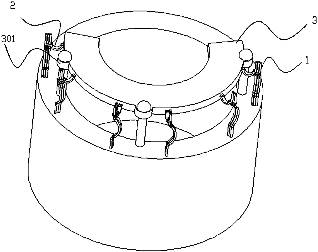
[0038] Such as Figure 1-Figure 2 As shown, the present invention provides a three-item asynchronous generator stator lead wire structure, including:

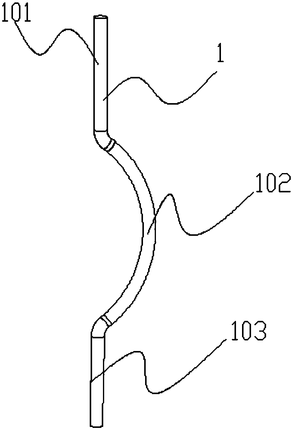
[0039] The single-turn buffered stator lead-out wire harness drawn from the stator winding, the single-turn buffered stator lead-out wire harness includes three stator lead-out wires 1, and the stator lead-out wire 1 includes a first vertical part 101, a curved part 102 and a second vertical part from top to bottom. Two vertical parts 103, the first vertical part 101 and the second vertical part 103 are arranged on the same horizontal plane, and the first vertical part 101 is connected to the special-shaped topology terminal 2 by resistance welding;

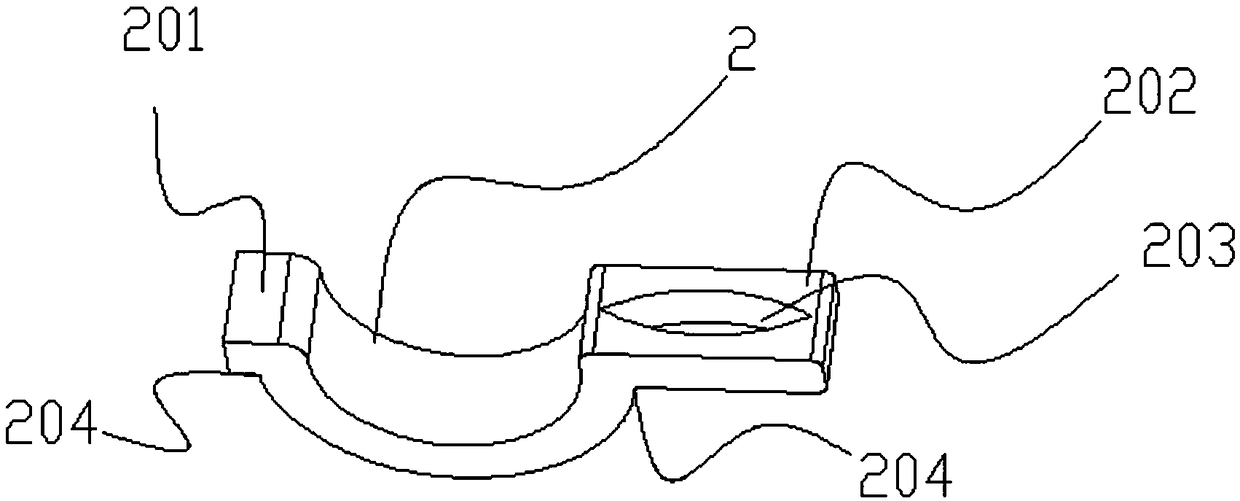
[0040] Such as Figure 3-Figure 4As shown, the special-shaped topology terminal 2 is set in a U shape, the top of...


PUM


Abstract

The invention discloses a stator lead-out wire connection structure of a three-phase asynchronous generator. The structure includes a single-turn buffered stator lead-out harness, an electrical connecting board, and special-shaped topological binding terminals. The single-turn buffered stator lead-out harness includes three stator lead-out wires, and each stator lead-out wire includes a first vertical part, a second vertical part and a bending part from top to bottom. One end of each special-shaped topological binding terminal is welded with the first vertical part of one corresponding statorlead-out wire, and the other end of each special-shaped topological binding terminal is connected with the electrical connecting board. According to the invention, the risk of fatigue damage of the stator lead-out wires under the condition of long-term vibration of a generator can be reduced, and the service life of the generator can be prolonged.

Description

technical field [0001] The invention relates to the field of generators, in particular to a connection structure for stator lead-out wires of a three-phase asynchronous generator. Background technique [0002] At present, in order to solve the noise at idling speed, the generators of small family cars on the market basically add a plastic gasket between the stator coil and the casing to change the natural frequency of the motor and solve the noise problem at idling speed. As a result, the stator coil will have a movement gap of 0.3 mm. When the engine is working, the stator coil will be driven to vibrate in the gap, so the problem of fatigue damage to the stator wire will occur. In order to solve this problem, the present invention provides a three-phase Asynchronous generator stator lead wire connection structure. [0003] Patent No. CN 106936268 A relates to a rectifier, which includes a positive rectifier plate, a negative rectifier plate and a connection plate between t...

Claims


Application Information

Patent Timeline
IPC IPC(8): H02K3/50G06F17/50
CPCH02K3/50G06F30/20
Inventor 李凤玲刘源荣见华范兴江
Owner CHANGSHA UNIVERSITY OF SCIENCE AND TECHNOLOGY
Learn More