Novel circular tube fixture
A round tube, a new type of technology, used in the field of mechanical round tube manufacturing and processing fixtures, mechanical manufacturing and processing, can solve problems such as inability to meet, low cutting efficiency, poor precision, etc., to facilitate installation and positioning, improve production efficiency, and simplify the installation process. Effect
- Summary
- Abstract
- Description
- Claims
- Application Information
AI Technical Summary
Problems solved by technology
Method used
Image
Examples
Embodiment 1
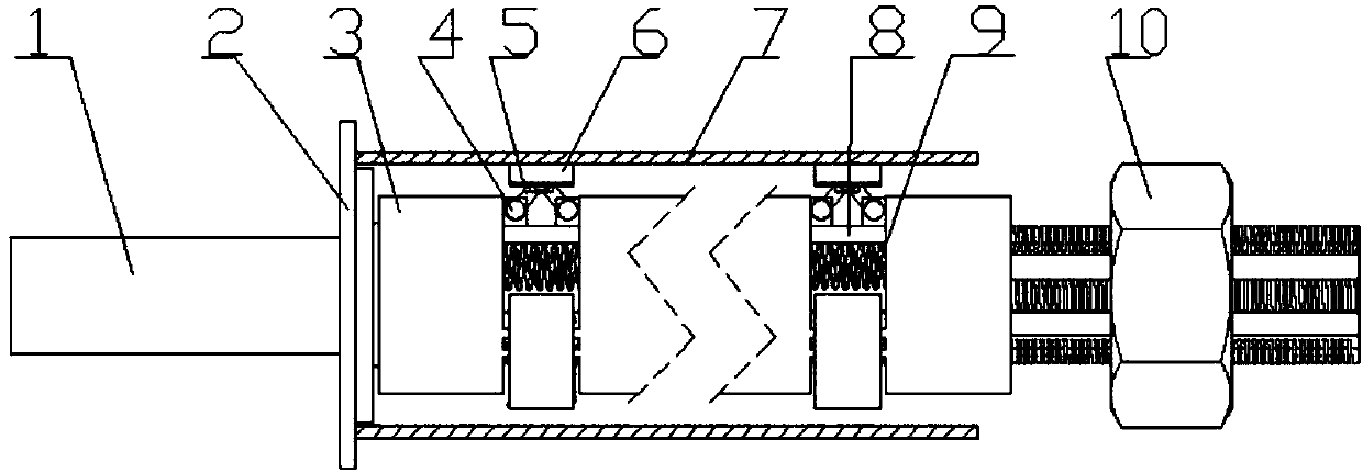
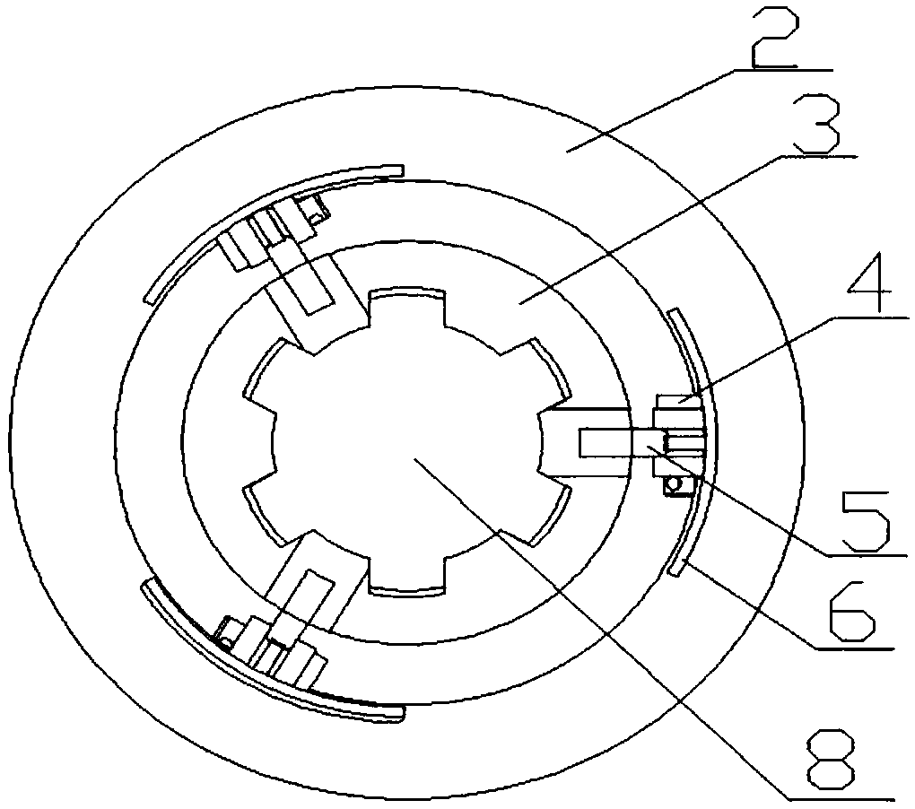
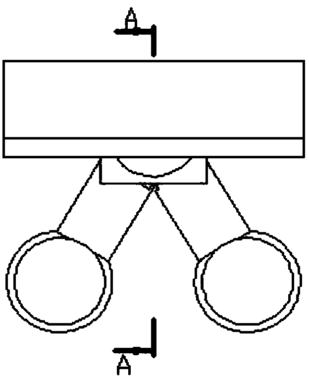
[0034] like figure 1 , figure 2 , image 3 , Figure 4 As shown, the new round pipe clamp consists of connecting shaft (1), positioning plate (2), inner spline (3), connecting pin (4), connecting rod (5), friction plate (6), outer spline shaft ( 8), spring (9) and clamping nut (10), the inner spline (3) cooperates with the outer spline shaft (8), and the inner spline (3) can be placed on the outer spline shaft (8) along the outer spline teeth ) slides along the axis, the inner spline (3) is hinged with one end of the connecting rod (5) through the connecting pin (4), and the friction plate (6) is hinged with the other end of the connecting rod (5) through the connecting pin. The clamping nut (10) cooperates with the thread on the right end of the external spline shaft (8), and the clamping nut (10) can push the internal spline (3) to slide along the external spline shaft (8) in turn during the tightening process. The pipe (7) is a round pipe to be processed, the wall thic...
Embodiment 2
[0037] like Figure 5 As shown, the new round pipe clamp consists of connecting shaft (1), positioning plate (2), inner spline (3), connecting pin (4), connecting rod (5), friction plate (6), outer spline shaft ( 8), spring (9) and clamping nut (10), the inner spline (3) cooperates with the outer spline shaft (8), and the inner spline (3) can be placed on the outer spline shaft (8) along the outer spline teeth ) slides along the axis, the inner spline (3) is hinged with one end of the connecting rod (5) through the connecting pin (4), and the friction plate (6) is hinged with the other end of the connecting rod (5) through the connecting pin. The clamping nut (10) cooperates with the thread on the right end of the external spline shaft (8), and the clamping nut (10) can push the internal spline (3) to slide along the external spline shaft (8) in turn during the tightening process. The pipe (7) is a round pipe to be processed, the wall thickness is 5 mm, the length of the pipe...
Embodiment 3
[0040] like Figure 5As shown, the new round pipe clamp consists of connecting shaft (1), positioning plate (2), inner spline (3), connecting pin (4), connecting rod (5), friction plate (6), outer spline shaft ( 8), spring (9) and clamping nut (10), the inner spline (3) cooperates with the outer spline shaft (8), and the inner spline (3) can be placed on the outer spline shaft (8) along the outer spline teeth ) slides along the axis, the inner spline (3) is hinged with one end of the connecting rod (5) through the connecting pin (4), and the friction plate (6) is hinged with the other end of the connecting rod (5) through the connecting pin. The clamping nut (10) cooperates with the thread on the right end of the external spline shaft (8), and the clamping nut (10) can push the internal spline (3) to slide along the external spline shaft (8) in turn during the tightening process. The pipe (7) is a round pipe to be processed, the wall thickness of the workpiece is 5 mm, the pi...
PUM
| Property | Measurement | Unit |
|---|---|---|
| length | aaaaa | aaaaa |
| diameter | aaaaa | aaaaa |
| diameter | aaaaa | aaaaa |
Abstract
Description
Claims
Application Information
 - R&D
- Intellectual Property
- Life Sciences
- Materials
- Tech Scout
- Unparalleled Data Quality
- Higher Quality Content
- 60% Fewer Hallucinations
Browse by: Latest US Patents, China's latest patents, Technical Efficacy Thesaurus, Application Domain, Technology Topic, Popular Technical Reports.
© 2025 PatSnap. All rights reserved.Legal|Privacy policy|Modern Slavery Act Transparency Statement|Sitemap|About US| Contact US: help@patsnap.com


