Mechanical arm and grabbing method thereof

A robotic arm and gripper technology, applied in the field of robotic arms, can solve problems such as damaged objects, inability to effectively grasp objects, and inability to grasp objects to designated positions, and achieve the effect of expanding the air outlet area and expanding the monitoring range.

Inactive Publication Date: 2019-03-26
ZHEJIANG SHUREN UNIV
View PDF8 Cites 3 Cited by
  • Summary
  • Abstract
  • Description
  • Claims
  • Application Information

AI Technical Summary

Problems solved by technology

[0005] Aiming at the deficiencies of the prior art, the present invention provides a mechanical arm and its grasping method, which can effectively grasp the object to be grasped to a designated position without causing damage to the object, and can improve control The heat dissipation efficiency of the electrical components in the device can better prevent dust from entering the controller, and the dust-proof net can be easily disassembled, etc., which solves the need to place the object in a specific position when the robotic arm grabs the object When the object deviates from the position, it will cause the robotic arm to be unable to effectively grasp the object, and may damage the object that needs to be clamped, and cannot grab the object that needs to be transported to the specified position, thus affecting the use of the robotic arm. The problem

Method used


Image

  • Mechanical arm and grabbing method thereof
  • Mechanical arm and grabbing method thereof
  • Mechanical arm and grabbing method thereof

Examples


Embodiment Construction

[0031] The following will clearly and completely describe the technical solutions in the embodiments of the present invention with reference to the accompanying drawings in the embodiments of the present invention. Obviously, the described embodiments are only some, not all, embodiments of the present invention. Based on the embodiments of the present invention, all other embodiments obtained by persons of ordinary skill in the art without making creative efforts belong to the protection scope of the present invention.

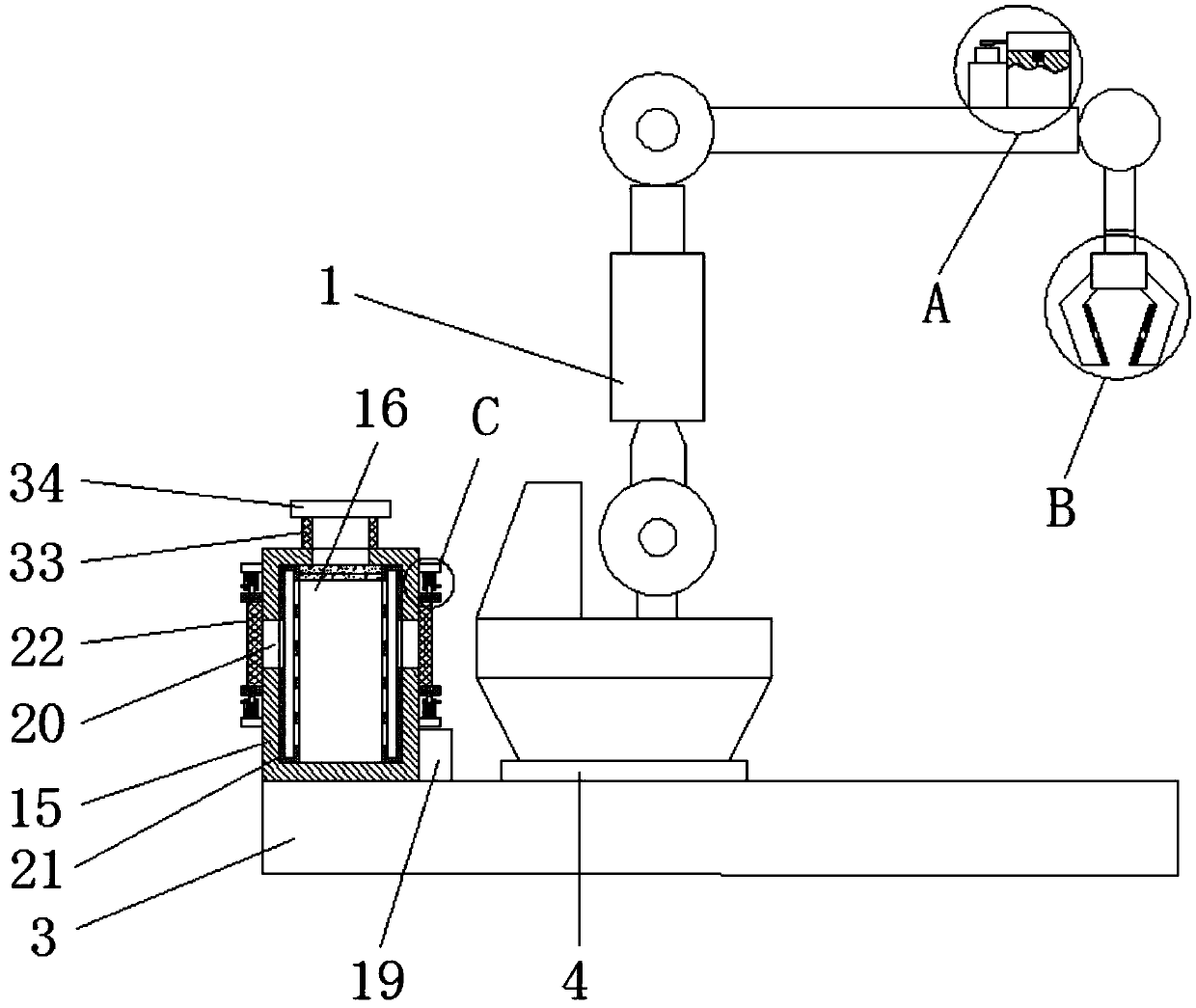
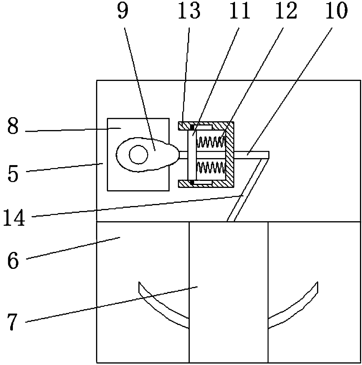
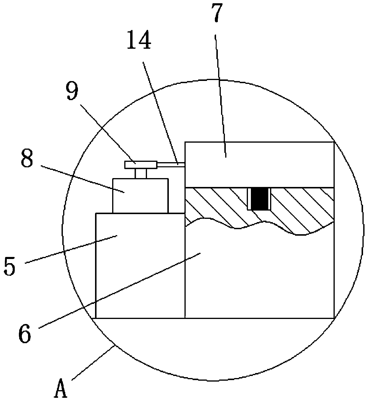
[0032] see Figure 1-5, a mechanical arm and its grasping method, comprising a mechanical arm body 1 and a gripper 2 installed on the mechanical arm body 1, an electric slide rail 3 is provided at the bottom of the mechanical arm body 1, and the top of the electric slide rail 3 is slidably connected There is a moving block 4, the top of the moving block 4 is fixedly connected with the bottom of the robot body 1, the top of the robot body 1 is fixedly connected...


PUM


Abstract

The invention relates to the technical field of mechanical arms and discloses a mechanical arm and a grabbing method thereof. The mechanical arm comprises a mechanical arm body and a gripper mounted on the mechanical arm body. The bottom of the mechanical arm body is provided with an electric sliding rail. A moving block is slidably connected to the top of the electric sliding rail. The top of themoving block is fixedly connected with the bottom of the mechanical arm body. The top of the mechanical arm body is fixedly connected with a first supporting block and a second supporting block. Thetop of the second supporting block is slidably connected with a camera. The bottom of the camera is fixedly connected with a first sliding block. The top of the second supporting block is provided with a first arc-shaped sliding groove connected with the first sliding block in a matched mode. Through the mechanical arm and the grabbing method thereof, an article to be grabbed can be effectively grabbed to a designated location without damage, and the cooling efficiency on electrical components in a controller can be improved; meanwhile, dust can be prevented from getting into the controller, and a dust screen can be disassembled and assembled conveniently.

Description

technical field [0001] The invention relates to the technical field of mechanical arms, in particular to a mechanical arm and a grasping method thereof. Background technique [0002] The robotic arm is a complex system with multiple inputs and multiple outputs, highly nonlinear, and strong coupling. Because of its unique operational flexibility, it has been widely used in industrial assembly, safety and explosion-proof and other fields. The manipulator is a complex system with uncertainties such as parameter perturbation, external interference and unmodeled dynamics. Therefore, there are uncertainties in the modeling model of the manipulator. For different tasks, it is necessary to plan the motion trajectory of the joint space of the manipulator, so as to cascade to form the end pose. [0003] When the existing robotic arm grabs the object, it needs to place the object in a specific position for grabbing. When the object deviates from the position, the robotic arm cannot ef...

Claims


Application Information

Patent Timeline
Patent Type & Authority Applications(China)
IPC IPC(8): B25J9/00B25J13/08B25J15/12B25J19/00
CPCB25J9/0009B25J13/08B25J13/081B25J15/12B25J19/0054
Inventor 胡峰俊
Owner ZHEJIANG SHUREN UNIV
Why Eureka
Try Eureka