Charging pile structure

A charging pile and charging plug technology, used in charging stations, electric vehicle charging technology, electric vehicles, etc., can solve the problems of short circuit risk safety, access to charging plugs, hidden dangers, etc., to avoid safety accidents, achieve rain protection, and ensure smooth The effect of charging

Inactive Publication Date: 2019-03-26
杭州欣卓科技有限公司
View PDF6 Cites 2 Cited by
  • Summary
  • Abstract
  • Description
  • Claims
  • Application Information

AI Technical Summary

Problems solved by technology

However, a large part of the current charging piles are installed outdoors. When it rains, if charging is performed, rainwater may enter the charging plug and charging socket, which may cause short circuit risks and potential safety hazards.

Method used


Image

  • Charging pile structure
  • Charging pile structure
  • Charging pile structure

Examples


Embodiment 1

[0044] Such as Figure 1 to Figure 12 as shown,

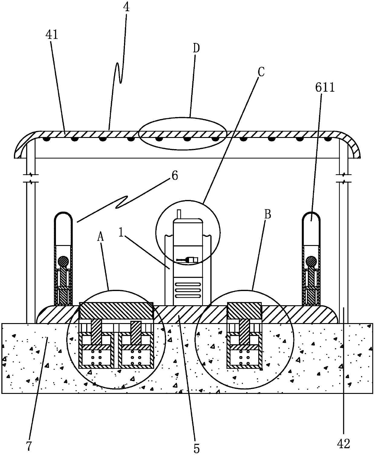
[0045] A charging pile structure, including a charging pile body 1 and a charging line, the charging pile body is provided with a housing space 1a, and the charging line includes an inner cable section connected to a power supply network, and an outer cable section in the accommodation space 2 and the charging plug seat 3 for docking with the charging socket of the electric vehicle, the inner cable section, the outer cable section and the charging plug seat are electrically connected in turn, the charging plug seat includes a plurality of metal pins 31, and the charging plug seat is located in the accommodation space middle;

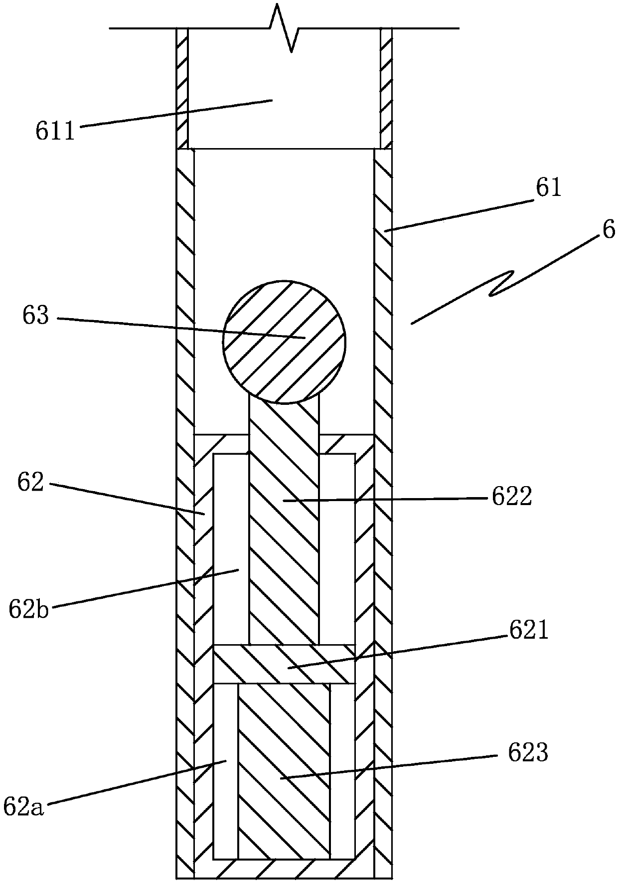
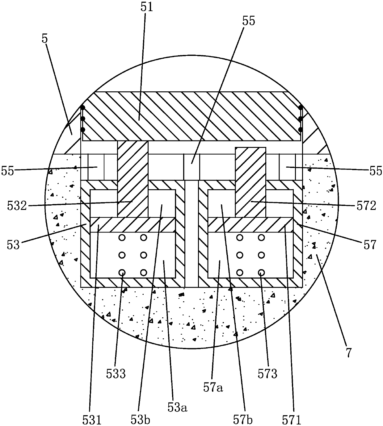
[0046] It also includes canopy 4, platform plate 5, two indicating mechanisms 6, the first ground trough on the ground 7 and the second ground trough on the ground, the platform plate is fixed to the ground, and the charging pile body is fixed on the ground , the canopy includes a ceiling 41 and several...

Embodiment 2

[0063] Embodiment 2: based on embodiment 1, such as Figure 13 to Figure 17 as shown,

[0064] The base is provided with a dust-proof plate 37 that slides and seals with the base. The axis of the inner cylinder is horizontal, and the sliding direction of the dust-proof plate is vertical. There is a moving magnet block 372, a fixed magnet block 341 which can be magnetically adsorbed to the moving magnet block is arranged on the middle cylinder, two plate through holes 37a are arranged on the dustproof plate, a part of pin holes correspond to a plate through hole, and the remaining pins The hole corresponds to another plate through hole, and all the plate through holes are sealed by the dust plate;

[0065] When the bottom surface of the first wheel pressure plate contacts the first ground limit block and the bottom surface of the second wheel pressure plate contacts the second ground limit block, the moving magnetic block is separated from the fixed magnetic block, the dust-pr...


PUM


Abstract

The invention discloses a charging pile structure. The charging pile structure comprises a charging pile body, a charging circuit, a canopy, a platform plate and two indicating mechanisms. The canopycomprises a ceiling. The charging pile body is provided with a terminal air pipe. The platform plate, the charging pile body, the terminal air pipe and two indicating pipes are located below the ceiling. A first ground groove is internally provided with a first main cylinder body, and a second ground groove is internally provided with a second main cylinder body. Each indicating mechanism comprises one indicating pipe and an indicating cylinder. The upper end of each indicating piston rod is provided with an indicating balancing weight located in the corresponding indicating pipe. When the bottom face of a first wheel pressing plate makes contact with first ground limiting blocks and the bottom face of a second wheel pressing plate makes contact with second ground limiting blocks, the bottommost points of the indicating balancing weights are higher than the highest points of the indicating pipes. The charging pile structure has the beneficial effects that an automobile to be charged can be assisted to arrive at an appropriate position, and therefore a rain-proof effect is achieved, it can be guaranteed that during charging, rainwater cannot enter a charging plug or a charging jack,the risk of short circuits is greatly reduced, and double protection for the charging structure and the electric automobile is achieved.

Description

technical field [0001] The invention belongs to the technical field of charging piles, and in particular relates to a charging pile structure. Background technique [0002] With the development of the times and the advancement of technology, new energy vehicles, especially electric vehicles, have been more and more widely used. An electric vehicle (BEV) refers to a vehicle that is powered by a vehicle-mounted power supply and uses a motor to drive the wheels, and meets the requirements of road traffic and safety regulations. Just like ordinary cars need to be refueled, electric vehicles also need to be charged. At present, the most important means of charging is to charge electric vehicles through charging piles. [0003] The input end of the charging pile is directly connected to the AC grid (power supply network), and the output end is equipped with a charging plug (or charging gun) for charging the electric vehicle. At present, the more common form of the charging plug ...

Claims


Application Information

Patent Timeline
Patent Type & Authority Applications(China)
IPC IPC(8): B60L53/31B60L53/16
CPCY02T10/70Y02T10/7072Y02T90/12Y02T90/14
Inventor 王铁霞
Owner 杭州欣卓科技有限公司
Why Eureka
Try Eureka