Support-free toolized formwork system applied to fabricated cast-in-place section and use method thereof

A formwork system and cast-in-place technology, applied in formwork/formwork/work frame, formwork/formwork/work frame connector, and on-site preparation of building components, can solve problems such as inability to meet green building requirements, Achieve the effect of saving construction operation space, good stability, and reducing the input of manpower and material resources

Active Publication Date: 2019-03-26
NO 2 CONSTR GRP CO LTD OF SHANGHAI CONSTR GRP
View PDF7 Cites 2 Cited by
  • Summary
  • Abstract
  • Description
  • Claims
  • Application Information

AI Technical Summary

Problems solved by technology

[0003] However, the prefabricated components are connected by pouring on the construction site, but the original wooden formwork and bent frames on the site are used. Today, under the social progress and development, it is no longer able to meet the concept of green buildings.

Method used


Image

  • Support-free toolized formwork system applied to fabricated cast-in-place section and use method thereof
  • Support-free toolized formwork system applied to fabricated cast-in-place section and use method thereof
  • Support-free toolized formwork system applied to fabricated cast-in-place section and use method thereof

Examples


Embodiment Construction

[0028] The present invention will be described in further detail below in conjunction with the accompanying drawings and specific embodiments. The technical content and features of the present invention will be described in detail below by referring to the illustrated embodiments in conjunction with the accompanying drawings. It should be further noted that all the drawings are in very simplified form and use imprecise scales, and are only used to facilitate and clearly assist the purpose of illustrating the embodiments of the present invention. For the convenience of description, the "up" and "down" described below are consistent with the directions of up and down in the drawings, but this should not be a limitation of the technical solution of the present invention.

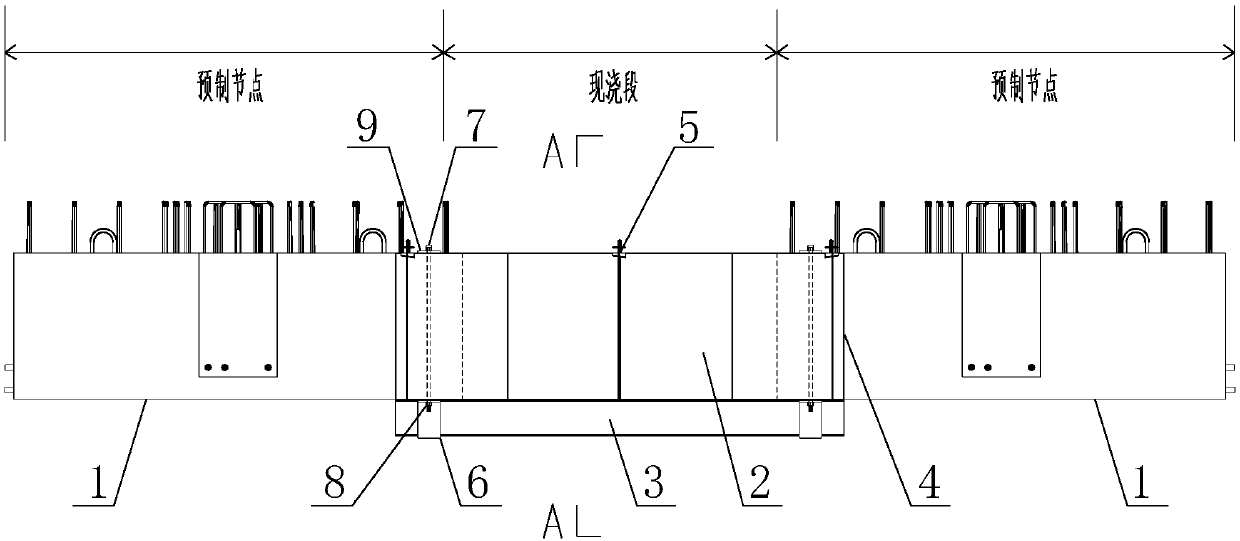
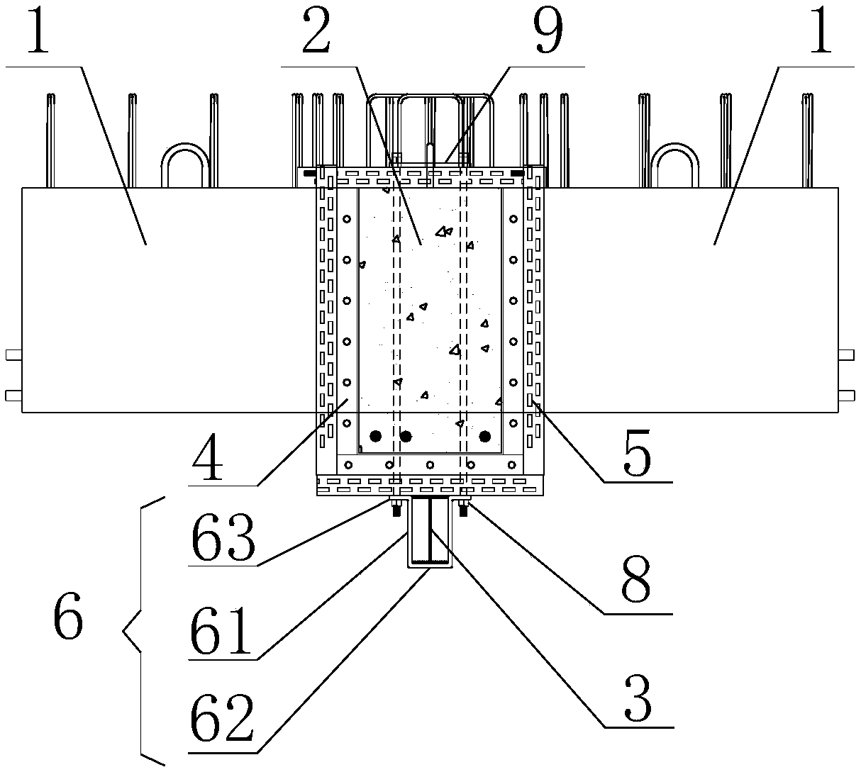
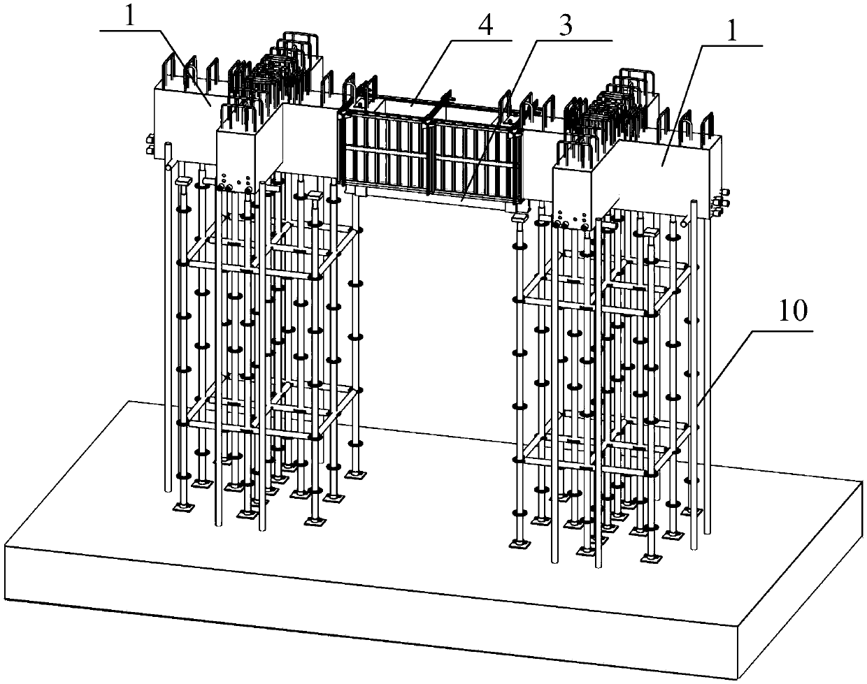
[0029] see Figure 1 to Figure 3 , this embodiment provides an unsupported tooled formwork system applied to an assembled cast-in-place section, which is used to pour a cast-in-place concrete beam section 2 fo...


PUM


Abstract

The invention discloses a support-free toolized formwork system applied to a fabricated cast-in-place section and a use method thereof and aims to solve the problem that in the prior art, a supportingframed bent needs to be erected under a cast-in-place section and accordingly a construction period is long, manpower and material input is large and the supporting framed bent occupies excessive construction space. By arranging lower hanging mechanisms on two fabrication nodes for butt joint of cast-in-place concrete beam sections to hang two ends of I-steel, the weights of clamps, formworks andthe cast-in-place concrete beam sections are borne by the I-steel and transferred by the I-steel to the two prefabrication nodes through the lower hanging mechanisms at both ends. The support-free toolized formwork system has the advantages of convenient construction and high efficiency and is good in stability and high in bearing capacity, the lower portion of the I-steel is not provided with asupporting framed bent, namely no supporting framed bent is arranged below the cast-in-place concrete beam sections, the construction operation space and the time and work amount of erection and dismantling of the supporting framed bent are effectively saved, the manpower and material input in the existing construction process is greatly decreased, and the environment-friendly construction requirements are met.

Description

technical field [0001] The invention relates to the technical field of prefabricated assembly construction, in particular to an unsupported tool-based formwork system applied to an assembly-type cast-in-place section and a method for using the same. Background technique [0002] With the development of modern industrial technology, building houses can be manufactured in batches and in sets like machine production. Just transport the prefabricated building components to the construction site and assemble them. Part of the components are prefabricated in a factory, and then the prefabricated part is formed by a specific connection method on site or a part of the concrete is poured on site to form the entire building. Such a building is called a prefabricated building. [0003] However, the prefabricated components are connected by on-site pouring, but the original construction methods such as wooden formwork and bent frames on the site cannot meet the concept of green buildin...

Claims


Application Information

Patent Timeline
Patent Type & Authority Applications(China)
IPC IPC(8): E04G13/04E04G17/18E04B1/20E04B1/21
CPCE04B1/20E04B1/21E04G13/04E04G17/18
Inventor 郭延义胡董超黄时锋赵欣卫军明黄飞祥祁真吴樟强廖志斌姜波
Owner NO 2 CONSTR GRP CO LTD OF SHANGHAI CONSTR GRP
Why Eureka
Try Eureka