Concave pressing block with slow release areas for peristaltic pump

A technology of peristaltic pump and slow-release zone, applied in the field of peristaltic pump, can solve the problem of peristaltic pump delivery fluctuation and other problems, achieve the effect of balanced force and prolong service life

Inactive Publication Date: 2019-03-26
郑州玄一机器人有限公司
View PDF0 Cites 1 Cited by
  • Summary
  • Abstract
  • Description
  • Claims
  • Application Information

AI Technical Summary

Problems solved by technology

[0003] During the pumping process of the peristaltic pump, since the rollers need to be released alternately, the liquid will be sucked back at the moment of release, resulting in a decrease in the output liquid at the outlet end, resulting in fluctuations in the delivery of the peristaltic pump

Method used


Image

  • Concave pressing block with slow release areas for peristaltic pump
  • Concave pressing block with slow release areas for peristaltic pump
  • Concave pressing block with slow release areas for peristaltic pump

Examples


Embodiment example 1

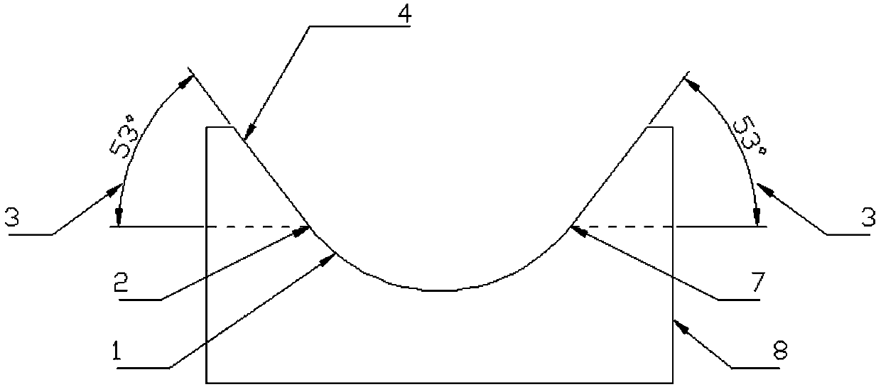
[0048] like figure 1 Shown is a schematic view of the structure of an embodiment of a concave compact with a sustained release area of ​​the present invention, including: arc surface 1, release point 2, inclination angle 3, large-angle slope 4, compression point 7, Briquetting body 8;

[0049] One side of the briquetting body 8 is an arc surface 1; one end of the arc surface 1 is a release point 2, and the other end of the arc surface 1 is a compression point 7; the release point 2 is a large-angle slope 4 outward; the compression point 7 is a large-angle slope 4 outward.

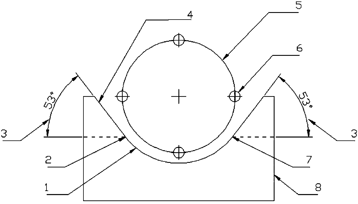
[0050] like figure 2 Shown is figure 1 A schematic diagram of the structure of a concave briquetting block with a slow release area used in conjunction with the runner of a peristaltic pump, including: arc surface 1, release point 2, inclination angle 3, large-angle slope 4, runner 5, roller 6. Compression point 7, briquetting body 8;

[0051] One side of the briquetting body 8 is an arc surface 1; on...

Embodiment example 2

[0066] like Figure 5 Shown is a schematic structural diagram of another embodiment of a concave briquetting block with a sustained release area of ​​the present invention, including: arc surface 1, release point 2, compression point 7, briquetting block body 8, involute line_slope10;

[0067] One side of the briquetting body 8 is an arc surface 1; one end of the arc surface 1 is a release point 2, and the other end of the arc surface 1 is a compression point 7; the release point 2 is outwardly an involute slope 10; the compression Point 7 is an involute slope 10 outward.

[0068] like Image 6 Shown is Figure 5 The schematic diagram of the structure of the concave briquetting block with a slow release area and the runner of the peristaltic pump shown, including: arc surface 1, release point 2, runner 5, roller 6, compression point 7, briquetting body 8. Involute slope 10;

[0069] One side of the briquetting body 8 is an arc surface 1; one end of the arc surface 1 is a ...

Embodiment example 3

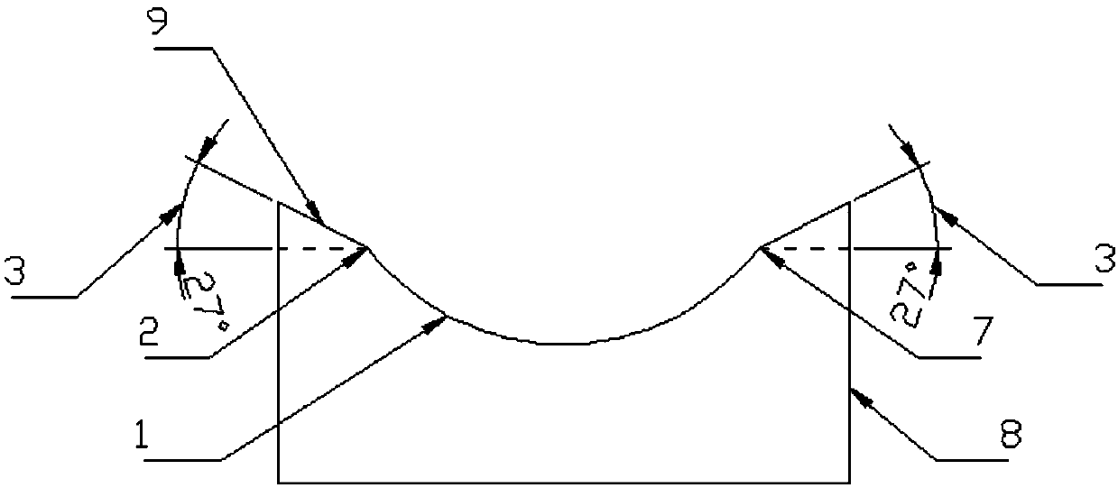
[0074] like Figure 7 Shown is a schematic structural diagram of another embodiment of a concave compact with a sustained release area of ​​the present invention, including: arc surface 1, release point 2, inclination angle 3, large-angle slope 4, and compression point 7 , briquetting body 8, involute slope 10;

[0075] One side of the briquetting body 8 is an arc surface 1; one end of the arc surface 1 is a release point 2, and the other end of the arc surface 1 is a compression point 7; the release point 2 is outwardly an involute slope 10; the compression Point 7 is a large-angle slope 4 outward.

[0076] like Figure 8 Shown is Figure 7 The schematic diagram of the structure of the concave briquetting block with a slow release area used in conjunction with the runner of the peristaltic pump, including: arc surface 1, release point 2, inclination angle 3, large-angle slope 4, runner 5, roller 6, Compression point 7, briquetting body 8, involute slope 10;

[0077] One ...


PUM


Abstract

The invention relates to a concave pressing block with slow release areas for a peristaltic pump. The concave pressing block with the slow release areas for the peristaltic pump comprises a pressing block body, one side of the pressing block body is an arc surface, and areas near the apex of at least one end of the arc surface are the slow release areas; and the slow release areas are involute oblique surfaces and/or large angle oblique surfaces and/or involute irregular surfaces. When the slow release areas are arranged at an outlet end, a roller wheel leaves a departure point, the longer slow release areas enable the roller wheel to gradually release the compression on a hose, and the hose gradually returns to an original state; the liquid reflux speed at the outlet end is slower, and the liquid flow rate at the outlet end fluctuates less; when the slow release areas are arranged at an inlet end, the longer slow release areas enable the roller wheel gradually tighten the hose, and the hose narrows slowly; the liquid reflux speed at the inlet end is slower, and the liquid flow rate at the inlet end fluctuates less; and when the slow release areas are arranged at both ends of the arc surface of the concave pressing block, the force of the hose is more balanced, and prolonging the service life of the hose is facilitated.

Description

technical field [0001] The invention relates to the field of peristaltic pumps, in particular to a concave briquetting block with a slow-release area for the peristaltic pump, a peristaltic pump head and a peristaltic pump. Background technique [0002] Peristaltic pump (Peristaltic Pump), also known as hose pump, is a new type of industrial pump, widely used in pharmaceutical, food, chemical and other industries, to transport some sensitive, viscous, strong corrosive, abrasive For grinding, high purity requirements, and media containing certain granular materials. A peristaltic pump is like pinching a fluid-filled hose with your finger, and the fluid in the tube moves forward as the finger slides forward. The peristaltic pump is also based on the same principle except that the fingers are replaced by rollers. Fluid is delivered by alternately squeezing and releasing the pump's elastic delivery hose. Just like pinching the hose with two fingers, with the movement of the f...

Claims


Application Information

Patent Timeline
Patent Type & Authority Applications(China)
IPC IPC(8): F04B43/12
CPCF04B43/1253
Inventor 石立公韩传超李国伟
Owner 郑州玄一机器人有限公司
Why Eureka
Try Eureka