Intelligent debugging system and method used for air conditioning equipment

A technology for air conditioning equipment and debugging systems, which is applied in lighting and heating equipment, heating and ventilation control systems, heating and ventilation safety systems, etc. problems, to achieve the effect of improving the efficiency of air conditioning debugging, convenient communication between personnel, and clear project progress

Inactive Publication Date: 2019-03-26
FOSHAN ZHONGGEWEI ELECTRONICS
View PDF14 Cites 7 Cited by
  • Summary
  • Abstract
  • Description
  • Claims
  • Application Information

AI Technical Summary

Problems solved by technology

[0002] In the traditional air-conditioning equipment debugging and control methods, especially in the electric control test project of the outdoor unit of the inverter air conditioner, there are common problems such as complex equipment hardware, many types of electric control parameters, and a large number of personnel participating in the test project. Therefore, how to quickly capture and solve problems in the debugging process The key points of debugging are the problems of electronic control fault protection points and the coordination of communication between project personnel; in addition, traditional debugging operations require debuggers to manually record electronic control parameters and fault protection information in the air-conditioning laboratory for a long time, which may cause errors in the records , and to obtain the electronic control parameter value requires a special measuring instrument to measure, the operation is inconvenient, the efficiency is low, and the wrong operation may cause the air conditioner electronic control to malfunction or even damage the electric control board and pose a hidden danger to personal safety

Method used


Image

  • Intelligent debugging system and method used for air conditioning equipment
  • Intelligent debugging system and method used for air conditioning equipment
  • Intelligent debugging system and method used for air conditioning equipment

Examples


Embodiment Construction

[0025] The present invention will be further described below in conjunction with specific examples.

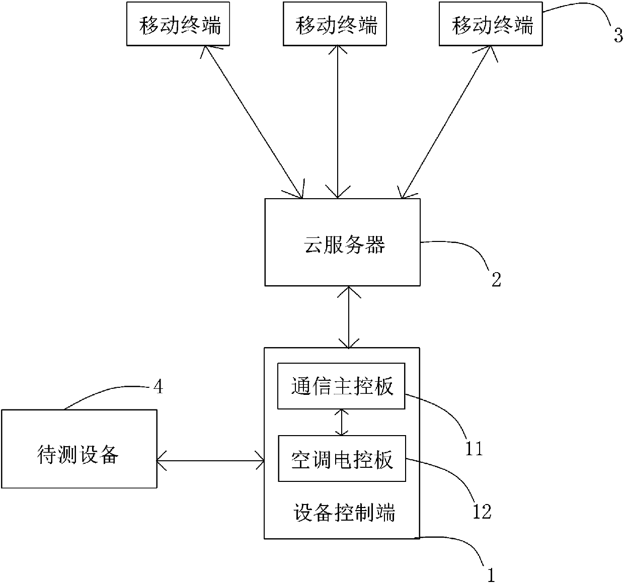
[0026] See attached Figure 1-8 , in this embodiment, an intelligent debugging system for air-conditioning equipment, including a device control terminal 1, a cloud server 2, and several mobile terminals 3, any mobile terminal 3 can be obtained through the cloud server 2 and the device control terminal 1 State information of the device under test 4, and adjust the operating status of the device under test 4, so as to achieve the purpose of real-time debugging of the device under test 4; specifically, in this embodiment, the device under test 4 is an outdoor unit of an inverter air conditioner, and the device control terminal 1 includes an air conditioner electric control board 12 and a communication main control board 11 that are installed in the outdoor unit and electrically connected to the outdoor unit components, wherein the air conditioner electric control board 12 is use...


PUM


Abstract

The invention provides an intelligent debugging system used for air conditioning equipment. The system comprises an equipment control terminal, a cloud server and multiple mobile terminals; the equipment control terminal is in dual-way communication with preset equipment to be detected, the equipment control terminal is used for obtaining state information of the equipment to be detected in real time and used for sending an equipment adjusting instruction to the equipment to be detected, the equipment control terminal is in dual-way communication with the cloud server, the equipment control terminal uploads the obtained state information to the cloud server in real time to be stored, any mobile terminal is in dual-way communication with the cloud server, any one mobile terminal is in connection and communication with the cloud server, a user can freely call the state information stored in the cloud server for display and transmit the equipment adjusting instruction to the equipment control terminal through the mobile terminal via the cloud server, adjusting parameters are modified in real time, and the aim of equipment running adjusting is achieved.

Description

technical field [0001] The present invention relates to the technical field of air-conditioning equipment systems, in particular to an intelligent debugging system and method for air-conditioning equipment. Background technique [0002] In the traditional air-conditioning equipment debugging and control methods, especially in the electric control test project of the outdoor unit of the inverter air conditioner, there are common problems such as complex equipment hardware, many types of electric control parameters, and a large number of personnel participating in the test project. Therefore, how to quickly capture and solve problems in the debugging process The key points of debugging are the problems of electronic control fault protection points and the coordination of communication between project personnel; in addition, traditional debugging operations require debuggers to manually record electronic control parameters and fault protection information in the air-conditioning...

Claims


Application Information

Patent Timeline
Patent Type & Authority Applications(China)
IPC IPC(8): F24F11/49F24F11/38G01M99/00
CPCF24F11/38F24F11/49G01M99/005G01M99/008
Inventor 高耀雅向小军邹俊立林崐唐娇
Owner FOSHAN ZHONGGEWEI ELECTRONICS
Why Eureka
Try Eureka