A real-time path planning method for UAV based on improved rrt

A real-time path planning and unmanned aerial vehicle technology, applied in the direction of navigation computing tools, etc., can solve problems such as limitations, large range, and reduced use efficiency, and achieve the effect of reducing the amount of calculation, reducing the range, and realizing online planning

Active Publication Date: 2021-05-07
智灵飞(北京)科技有限公司
View PDF8 Cites 0 Cited by
  • Summary
  • Abstract
  • Description
  • Claims
  • Application Information

AI Technical Summary

Problems solved by technology

[0006] (1) Algorithms in the prior art are only applicable to global planning, resulting in restrictions, inconvenient operation, and reduced use efficiency
[0007] (2) In the existing technology, random exploration of the entire space is required, the scope of random exploration is large, and the amount of calculation increases, so online planning cannot be effectively realized
Therefore, it is impossible to obtain a global map in advance, and thus cannot perform global path planning
This makes the global planning method limited in application

Method used


Image

  • A real-time path planning method for UAV based on improved rrt
  • A real-time path planning method for UAV based on improved rrt
  • A real-time path planning method for UAV based on improved rrt

Examples


Embodiment 1

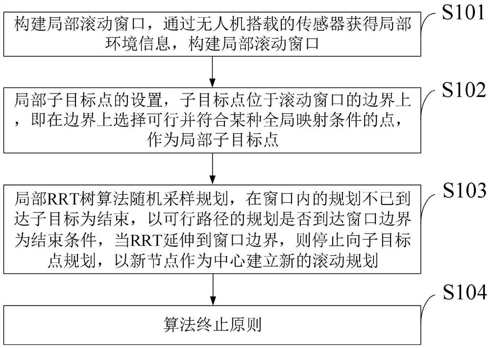
[0092] 1. Build a partial scrolling window

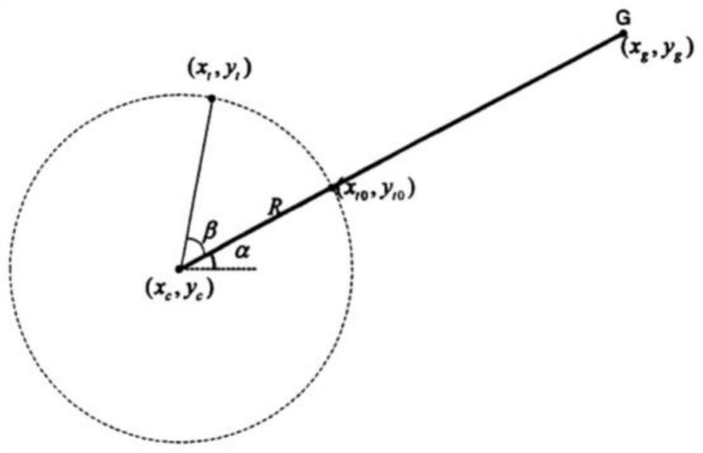
[0093] The local environmental information is obtained through the sensors carried by the UAV, and the planning window is driven in a periodic form. The window area of ​​each planning is defined as Win(q_R(t))={p|p∈C,d(q, q_R(t))≤R}, q_R(t) represents the center of the rolling window, R is the radius of the rolling window, generally the detection radius of the sensor. The aforementioned window is also referred to as the field of view of the drone.

[0094] Since the drone is in the process of real-time route planning and autonomous navigation, it is best to maintain a certain speed and fly continuously without stopping to wait for the next window planning to generate a path before proceeding. Therefore, in order to fly continuously, it is necessary to plan the next window in advance before reaching the local sub-target point, and take the current planned target point as the center of the next planning window. That is, after the ne...

Embodiment 2

[0114] The general flow of the rolling RRT algorithm provided by the embodiment of the present invention is as follows:

[0115] (1) initialize the variables of the RRT tree in the rolling window;

[0116] (2) judge whether it is located in the rolling window, if it is then go to step 3, not go to step 4;

[0117] (3) As the target point, randomly generate nodes on the boundary

[0118] (4) Obtain local sub-target points on the rolling window boundary, and generate random nodes on the boundary;

[0119] (5) Select the nearest tree node in the current tree species, and generate nodes according to a certain step size;

[0120] (6) Collision detection is performed on the connection line;

[0121] (7) Judging whether it is in the flyable zone and there is no obstacle distribution on the connection line, if not satisfied, return to step 2, and if satisfied, go to step 6;

[0122] (8) will join the tree list, judge to arrive, if not then go to step 9; Yes then end the algorithm;...


PUM


Abstract

The invention belongs to the field of unmanned aerial vehicle operation technology, and discloses a real-time path planning method for unmanned aerial vehicles based on improved RRT, which includes constructing a local rolling window; setting of local sub-target points; random sampling planning of local RRT tree algorithm; algorithm termination principle. The invention improves and fuses the algorithm originally only applicable to the global planning, uses locally known environmental information to construct a window, determines sub-target points through a certain method, and uses the global planning algorithm to explore in this environment. As the window scrolls forward, the environmental information in the window is constantly updated to realize planning, mapping and feedback, and finally reach the target point. For the RRT algorithm, compared with global planning, this improved method based on rolling windows does not need to randomly explore the entire space, but limits the planning to countless windows that are continuously updated, and the scope of random exploration is reduced. Calculation The amount is reduced, and online planning can be realized.

Description

technical field [0001] The invention belongs to the technical field of unmanned aerial vehicles, and in particular relates to an improved RRT-based real-time path planning method for unmanned aerial vehicles. Background technique [0002] At present, the existing technology commonly used in the industry is as follows: the rapid expansion random tree (RRT) path planning method has many advantages such as strong adaptability, fast generation speed, and complete probability, but it must rely on the known global map to perform planning. Therefore, generally speaking, RRT is a global planning method, which cannot realize real-time route generation of UAVs. However, with the widespread application of UAVs, it is not enough to only consider global static obstacles in the indoor task environment. There are uncertain and dynamic obstacles in the indoor environment, and corresponding obstacle avoidance strategies should also be studied. Local planning is to collect local information...

Claims


Application Information

Patent Timeline
Patent Type & Authority Patents(China)
IPC IPC(8): G01C21/20
CPCG01C21/20
Inventor 李璟璐丁久辉
Owner 智灵飞(北京)科技有限公司
Why Eureka
Try Eureka