Pure-shear loading device and method for tubular product

A loading device, pure shearing technology, applied in the direction of measuring device, using stable shear force to test material strength, analyzing materials, etc., can solve problems such as no practical application significance

Active Publication Date: 2019-03-26
HARBIN INST OF TECH +1
View PDF4 Cites 5 Cited by
  • Summary
  • Abstract
  • Description
  • Claims
  • Application Information

AI Technical Summary

Problems solved by technology

[0008] According to the mechanics of materials, if the pipe is divided into upper and lower parts by the section passing through the pipe axis, a pair of parallel forces with opposite directions are applied to the upper and lower parts, as shown in figure 1 As shown, at this time, the material passing through the secti...

Method used


Image

  • Pure-shear loading device and method for tubular product
  • Pure-shear loading device and method for tubular product
  • Pure-shear loading device and method for tubular product

Examples


Embodiment 1

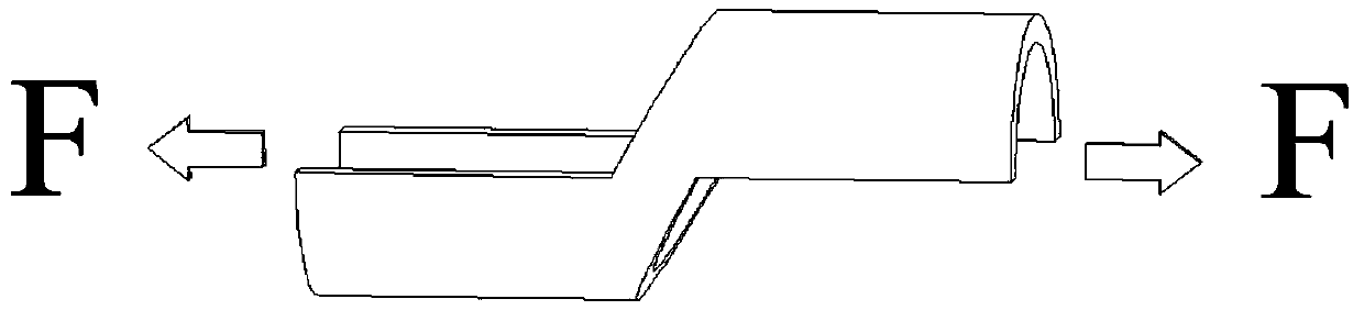
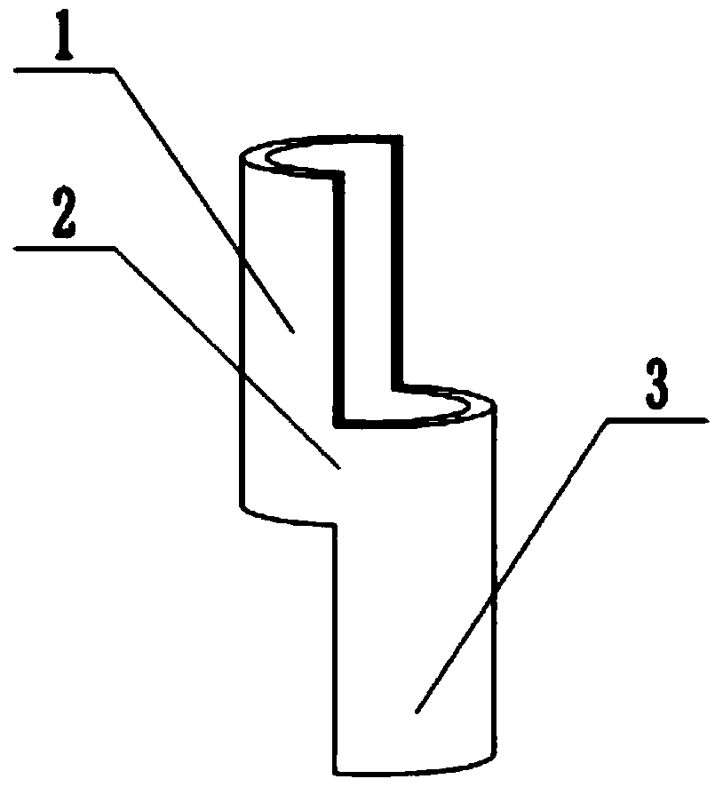
[0034] Such as Figure 2-Figure 5 Shown: This embodiment provides a pure shear loading device for pipes, including pipes to be tested, and the cross-section of the pipes to be tested is circular or non-circular. In this embodiment, the cross-section of the pipe to be tested is circular. The outer diameter of the circular pipe is 62mm, the wall thickness is 1mm, and the material is 5A02 aluminum alloy. The pipe material to be tested includes a first half pipe 1 , a whole pipe 2 and a second half pipe 3 connected in sequence, and the first half pipe 1 and the second half pipe 3 have the same size. The connection between the first half pipe 1 and the whole pipe 2 and the connection between the second half pipe 3 and the whole pipe 2 can also be provided with cutouts, the size of the cutouts is the same, or no cutouts can be provided. The first mandrel 4 is arranged in the first half pipe 1, and the second mandrel 5 is arranged in the second half pipe 3. The structures and sizes...

Embodiment 2

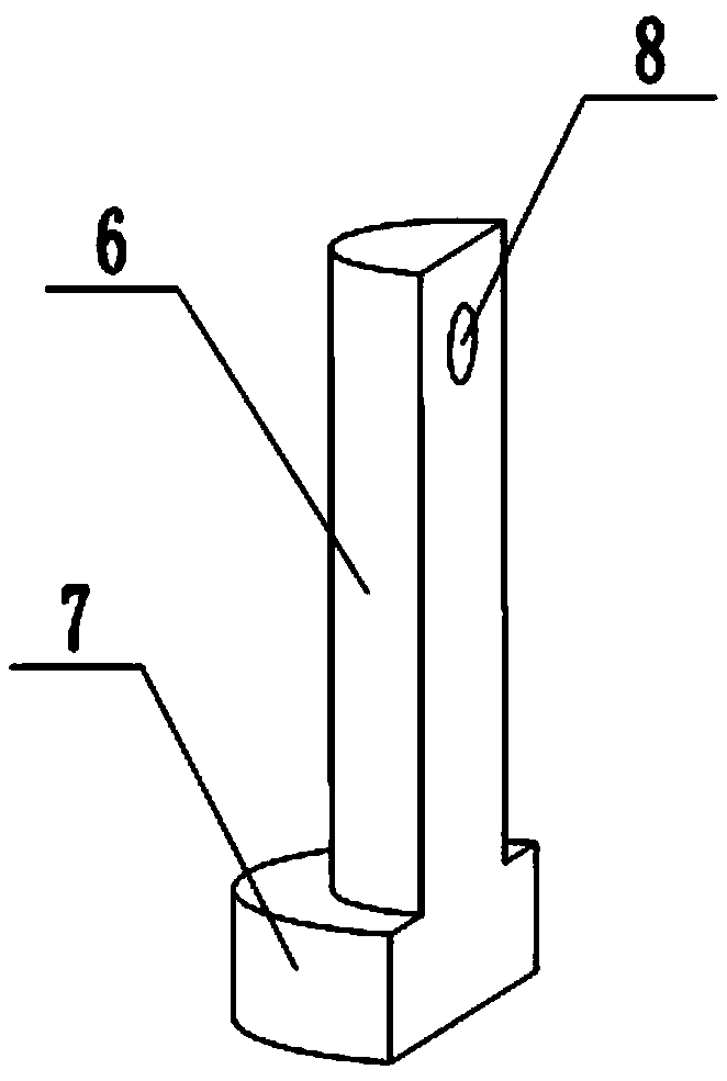
[0042] Such as Figure 2-Figure 6 As shown: the difference between this embodiment and the first embodiment is that: in this embodiment, the upper end of the first mandrel 4 is connected with a first force transmission part 9, and the first force transmission part 9 includes a first loading part 11 and a first loading part 11 connected to each other. The third connecting part 12, the third through hole 13 is arranged on the third connecting part 12, the third through hole 13 and the first through hole 8 are fixedly connected by the positioning pin 15, and the fourth through hole is arranged on the first loading part 11 14. The fourth through hole 14 is perpendicular to the first through hole 8, and the fourth through hole 14 is used to connect with the testing machine; the upper end of the first mandrel 4 is connected with the second force transmission part 10, and the second force transmission part 10 includes a second loading part and a fourth connecting part that are connec...


PUM

PropertyMeasurementUnit
Outer diameteraaaaaaaaaa
Wall thicknessaaaaaaaaaa
Shear strengthaaaaaaaaaa

Abstract

The invention discloses a pure-shear loading device and method for a tubular product. A first core shaft penetrates into a first half pipe; a second core shaft penetrates into a second half pipe; thesize of the first core shaft is matched with the size of the first half pipe; the size of the second core shaft is matched with the size of the second half pipe; a first connection part of the first core shaft and a second connection part of the second core shaft are loaded; a first protruding part and a second protruding part are used for transmitting a force to a tubular product to be detected,so that a material, which is located on the same plane of a right plane or a left plane of the first half pipe and the left plane or the right plane of the second half pipe, on a whole pipe is at a pure-shear stress state. The pure-shear loading device disclosed by the invention is simple in structure; the first core shaft and the second core shaft, which have special designs, are used for inhibiting the rotation of the tubular product to be detected, which is difficult to control, in a shear deformation process; and the material, which is located on the same plane of the right plane or the left plane of the first half pipe and the left plane or the right plane of the second half pipe, on the whole pipe can be at the stable pure-shear stress state in a whole deformation process.

Description

technical field [0001] The invention relates to the technical field of pipe mechanical performance testing, in particular to a pipe pure shear loading device and method. Background technique [0002] Pipes are widely used in the production of the national economy, and the cross-sectional shapes are round, square and irregular. In addition to being directly used as load-bearing components, tubular parts after plastic processing are often used as structural parts. Typical forming methods include high-pressure forming of pipes and bending of pipes. Representative parts include automobile body chassis structures, various aircraft and Curved axis piping in automobiles, etc. [0003] In order to avoid failure phenomena such as wrinkling and cracking of pipes during plastic processing, it is necessary to understand the mechanical properties of the pipes used, use the results of computer numerical simulation to reasonably design and optimize the forming process parameters, and effe...

Claims


Application Information

Patent Timeline
IPC IPC(8): G01N3/24
CPCG01N3/24G01N3/04G01N2203/0266G01N2203/0641G01N3/02G01N2203/0025
Inventor 王小松胡卫龙苑世剑
Owner HARBIN INST OF TECH
Why Eureka
Try Eureka