Fault restarting method for parallel multi-terminal direct-current transmission line

A DC transmission line, multi-terminal DC technology, applied in the direction of emergency protection circuit devices, electrical components, power transmission AC network, etc., to achieve the effect of rapid extinguishment

Active Publication Date: 2019-03-26
NR ELECTRIC CO LTD +1
View PDF8 Cites 4 Cited by
  • Summary
  • Abstract
  • Description
  • Claims
  • Application Information

AI Technical Summary

Problems solved by technology

[0006] The purpose of the present invention is to provide a parallel multi-terminal direct current transmission line fault restart method to solve the problem of quickly extinguishing the fault current and restoring the power supply of the parallel multi-terminal direct current transmission system after a certain direct current transmission line fails

Method used


Image

  • Fault restarting method for parallel multi-terminal direct-current transmission line
  • Fault restarting method for parallel multi-terminal direct-current transmission line
  • Fault restarting method for parallel multi-terminal direct-current transmission line

Examples


Embodiment 1

[0054] Figure 4 It is a flowchart of a fault restart method for parallel multi-terminal direct current transmission lines, which includes the following steps:

[0055] Step 1, select the branch station connected to the faulty DC transmission line as the leading station for restarting the faulty DC transmission line;

[0056] Step 2: Immediately after the DC transmission line fault occurs, all converter stations with LCC converters adjust the ignition angle to be greater than 150 degrees and less than 180 degrees, and all converter stations with VSC converters control the DC voltage of the station to zero or immediate temporary closure;

[0057] Step 3, all terminal stations with VSC converters connected to the main station isolate the DC transmission lines from themselves through switchgear;

[0058] Step 4, the branch stations of all terminal systems connected to the main station isolate the DC transmission lines from their own systems through switchgear;

[0059] Step 5,...

Embodiment 2

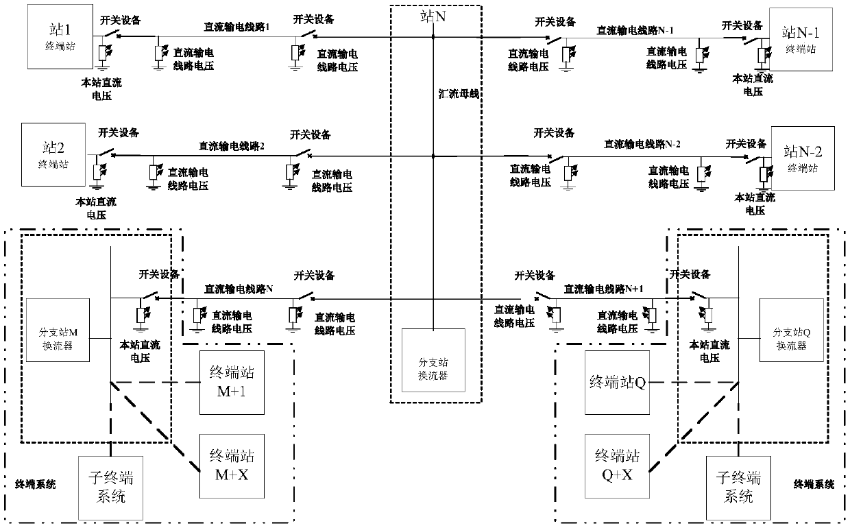
[0073] Related fault points and switchgear such as Figure 5 shown.

[0074] Assuming that instantaneous fault F1 occurs on DC transmission line 1, DC transmission line 1 connects station 1 of the terminal station and main station N, and station 1 is a converter station with a VSC converter. After the protection action of the DC transmission line, the converter station with the LCC converter in the entire parallel multi-terminal DC transmission system immediately adjusts the ignition angle to be greater than 150 degrees and less than 180 degrees, and the converter station with the VSC converter controls the direct current of the station. Voltage to zero (or immediately and temporarily blocked); all terminal stations with VSC converters connected to the leading station pull the switchgear between the station and the DC transmission line to isolate the DC transmission line from itself (for example, station 1 pulls Open the switchgear K11); the branch stations of all terminal sy...

Embodiment 3

[0076] Related fault points and switchgear such as Figure 5 shown.

[0077] Assuming that permanent fault F1 occurs on DC transmission line 1, DC transmission line 1 connects station 1 of the terminal station and main station N, and station 1 is a converter station with a VSC converter. After the protection action of the DC transmission line, the converter station with the LCC converter in the entire parallel multi-terminal DC transmission system immediately adjusts the ignition angle to be greater than 150 degrees and less than 180 degrees, and the converter station with the VSC converter controls the direct current of the station. Voltage to zero (or immediate temporary blocking) so that the fault current at the fault point of the DC transmission line is quickly extinguished; all terminal stations with VSC converters connected to the main station open the switchgear between the station and the DC transmission line to The DC transmission line is isolated from itself (for ex...


PUM


Abstract

The invention discloses a fault restarting method for a parallel multi-terminal direct-current transmission line. The method comprises: a branch station connected with a faulty direct-current transmission line is selected as a leading station for fault restarting of the direct-current transmission line; all convertor stations control converters to extinguished fault currents and then the leading station is isolated from a terminal station with a VSC converter and a branch station of a terminal system by using switching equipment; and then the main station starts to establish a direct-current transmission line voltage, the connection and power of the whole parallel multi-terminal direct-current transmission system are restored if the direct-current transmission line voltage is established successfully, the faulty direct-current transmission line is isolated if the direct-current transmission line voltage establishment fails, and the connection and power of the rest of parallel multi-terminal direct-current transmission system are restored. With the method disclosed by the invention, after a direct-current transmission line fault occurs, the fault current is extinguished rapidly andthe power supply of the parallel multi-terminal direct-current transmission system is restored to the greatest extent; and the influence of station-to-station communication existence among all convertor stations is avoided.

Description

technical field [0001] The invention belongs to the field of high-voltage, ultra-high-voltage and ultra-high-voltage direct current transmission, and in particular relates to a fault restart method for parallel multi-terminal direct current transmission lines. Background technique [0002] With the continuous development of power electronic devices and the wide application of DC transmission technology, parallel multi-terminal DC transmission system has become a research hotspot. Parallel multi-terminal DC transmission has multiple DC transmission lines. When a line fault occurs, it is necessary to quickly clear the fault and restore the power supply of the parallel multi-terminal DC transmission system. [0003] Such as figure 1 As shown, taking the parallel N-terminal DC power transmission system as an example, converter station 1 to converter station N-1 are connected to the busbar of converter station N through the DC transmission line, where it is defined that converte...

Claims


Application Information

Patent Timeline
Patent Type & Authority Applications(China)
IPC IPC(8): H02J3/36H02H7/26
CPCH02H7/261H02H7/268H02J3/36Y02E60/60
Inventor 杨建明王永平董云龙鲁江张庆武王杨正徐斌李广宇俞翔黄如海
Owner NR ELECTRIC CO LTD
Why Eureka
Try Eureka