
Detection device and detection method for electronic equipment disassembly detection, electronic equipment

A technology for detection devices and electronic equipment, applied in measuring devices, detecting faulty computer hardware, electric/magnetic exploration, etc., can solve problems such as damage to airtightness, damage to labels, user disputes, etc., and achieve accurate detection results

Active Publication Date: 2021-01-05
MOBVOI INFORMATION TECH CO LTD
View PDF9 Cites 0 Cited by
  • Summary
  • Abstract
  • Description
  • Claims
  • Application Information

AI Technical Summary

Problems solved by technology

When the user disassembles the machine by himself and destroys the label, the manufacturer of the electronic device will refuse to provide warranty service
Moreover, the dustproof and waterproof functions provided by traditional electronic equipment will destroy the airtight characteristics after disassembly and assembly by users themselves, resulting in weakening or even failure of the dustproof and waterproof functions of electronic equipment.
[0004] However, the tamper-proof label cannot accurately reflect whether the electronic device is actually disassembled
Moreover, the tamper-proof label is easy to be accidentally damaged and forged during use, so that electronic equipment manufacturers cannot judge whether the user really disassembles the machine, and misjudgment will occur, resulting in disputes with users
[0005] In addition, in order to prevent users from disassembling the equipment, some electronic equipment will use some anti-disassembly structures and one-way anti-disassembly screws, which greatly reduces the maintainability of electronic equipment and increases the maintenance cost.

Method used


Image

  • Detection device and detection method for electronic equipment disassembly detection, electronic equipment
  • Detection device and detection method for electronic equipment disassembly detection, electronic equipment
  • Detection device and detection method for electronic equipment disassembly detection, electronic equipment

Examples


Embodiment Construction

[0031] Exemplary embodiments of the present disclosure will be described in more detail below with reference to the accompanying drawings. Although exemplary embodiments of the present disclosure are shown in the drawings, it should be understood that the present disclosure may be embodied in various forms and should not be limited by the embodiments set forth herein. Rather, these embodiments are provided for more thorough understanding of the present disclosure and to fully convey the scope of the present disclosure to those skilled in the art.

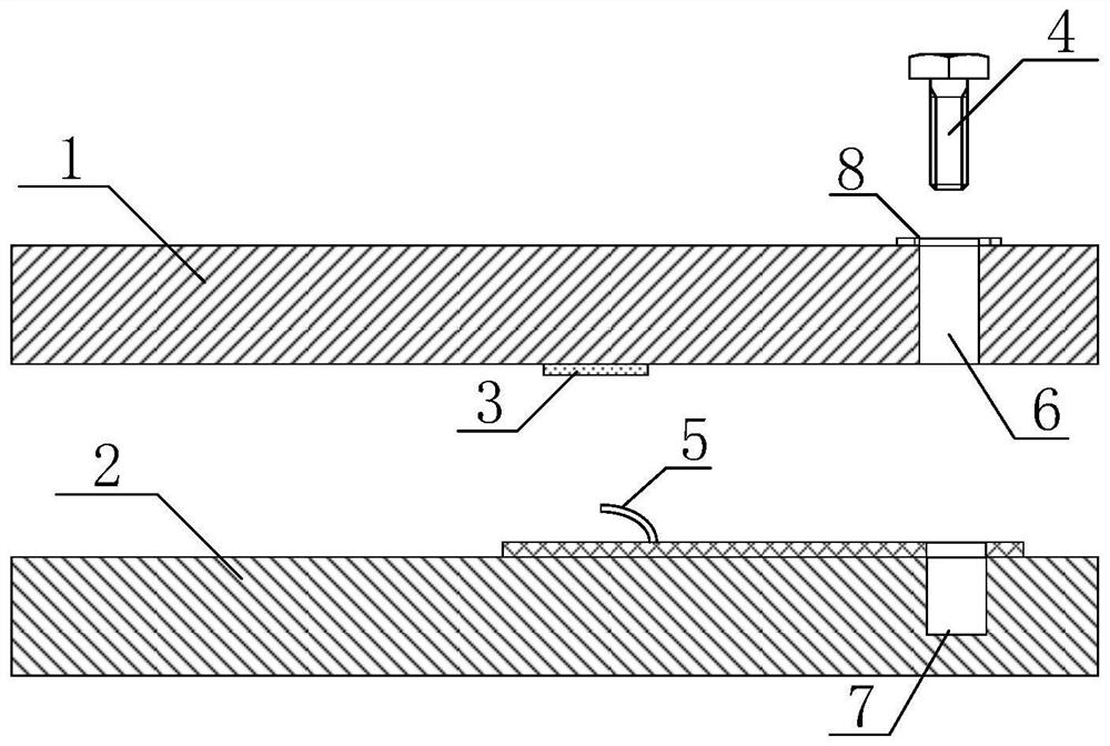
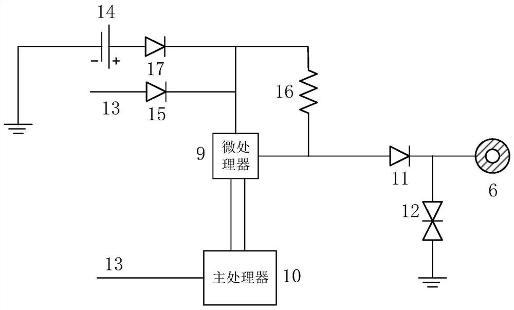
[0032] figure 1 A schematic structural diagram of a detection device according to an embodiment of the present invention is shown. Such as figure 1 As shown, the detection device includes: a circuit board 1 , a bracket 2 for supporting the circuit board 1 , a ground contact 3 , a conductive screw 4 and a connector 5 . The circuit board 1 is provided with conductive vias 6 . The bracket 2 is provided with conductive vias 7 at pos...


PUM


Abstract

One embodiment of the invention provides a detection device for electronic equipment disassembly detection, which comprises a circuit board, a support for supporting the circuit board, a grounding contact, a conductive screw and a connector. The circuit board is provided with a conductive through hole. The support is provided with a conductive via hole in a position corresponding to the position of the conductive through hole. The connector is arranged on one side of the support near the circuit board, and is electrically connected with the conductive via hole. The grounding contact is arranged on one side of the circuit board near the support, and is electrically connected with the connector. The conductive screw is used for passing through the conductive through hole and the conductive via hole. The other embodiments of the invention provide a piece of electronic equipment and a detection method thereof. By using the detection device of the invention, the detection personnel can knowthe disassembly situation and judge whether the electronic equipment has been disassembled before through a computer. Thus, the disassembly situation of the electronic equipment can be accurately detected, and the maintenance cost of the electronic equipment can be reduced.

Description

technical field [0001] The invention relates to the technical field of electronic equipment detection, in particular to a detection device and a detection method for electronic equipment disassembly detection, and electronic equipment. Background technique [0002] At present, electronic devices are becoming more and more popular, penetrate into every aspect of life, and bring many conveniences to people's life. The volume of electronic equipment is getting smaller and smaller, and the internal structure design is becoming more and more compact, and many electronic equipment use built-in batteries, taking into account functions such as dustproof and waterproof. [0003] The applicant found that because traditional electronic equipment does not allow users to disassemble it by themselves, anti-disassembly labels are affixed to the joints of the electronic equipment's casing or on the fixing screws. When the user disassembles the device by himself and destroys the label, the ...

Claims


Application Information

Patent Timeline
Patent Type & Authority Patents(China)
IPC IPC(8): H05K7/14H05K1/11G01V3/00G06F11/22
CPCG01V3/00G06F11/2247H05K1/115H05K7/1417
Inventor 孙雷助
Owner MOBVOI INFORMATION TECH CO LTD
Learn More