
Gluing equipment for assembling electronic components

A technology for electronic components and gluing, applied in coating, spraying device, device for applying liquid to the surface, etc., can solve problems such as glue can not be extruded in time, reduce practicability, and uneven glue application

Inactive Publication Date: 2019-03-29
郑州亨特利电子科技有限公司
View PDF0 Cites 2 Cited by
  • Summary
  • Abstract
  • Description
  • Claims
  • Application Information

AI Technical Summary

Problems solved by technology

[0003] The gluing equipment currently used for electronic component assembly has certain defects. It lacks the function of automatic glue extrusion, which causes the glue to not be squeezed out in time during the movement of the storage tube, resulting in uneven glue application, resulting in poor pasting effect, and lack of scraping. The glue function makes it inconvenient to clean the glue after it dries up on the rubber roller, which leads to the unreliable bonding of the rubber roller and the electronic components, lack of convenient placement of the glue bottle, and the inability to replace the glue bottle in time, reducing the practicality

Method used


Image

  • Gluing equipment for assembling electronic components
  • Gluing equipment for assembling electronic components
  • Gluing equipment for assembling electronic components

Examples


Embodiment Construction

[0028] The following will clearly and completely describe the technical solutions in the embodiments of the present invention with reference to the accompanying drawings in the embodiments of the present invention. Obviously, the described embodiments are only some, not all, embodiments of the present invention. Based on the embodiments of the present invention, all other embodiments obtained by persons of ordinary skill in the art without making creative efforts belong to the protection scope of the present invention.

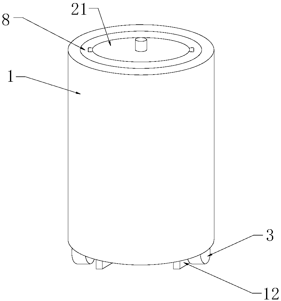
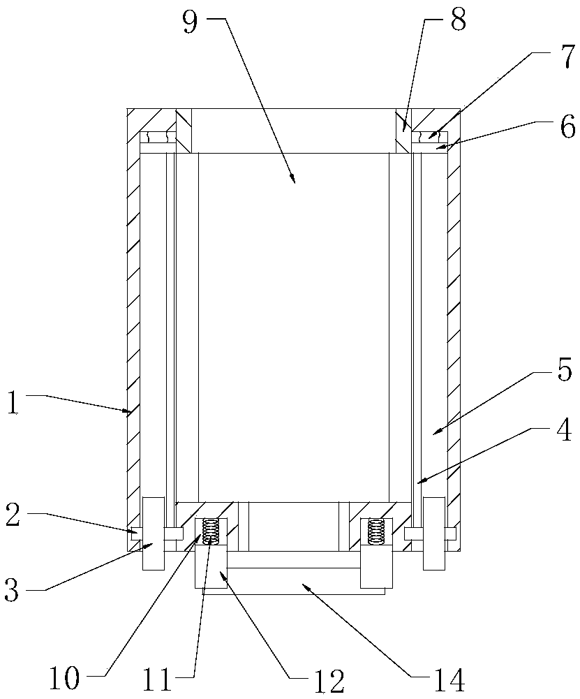
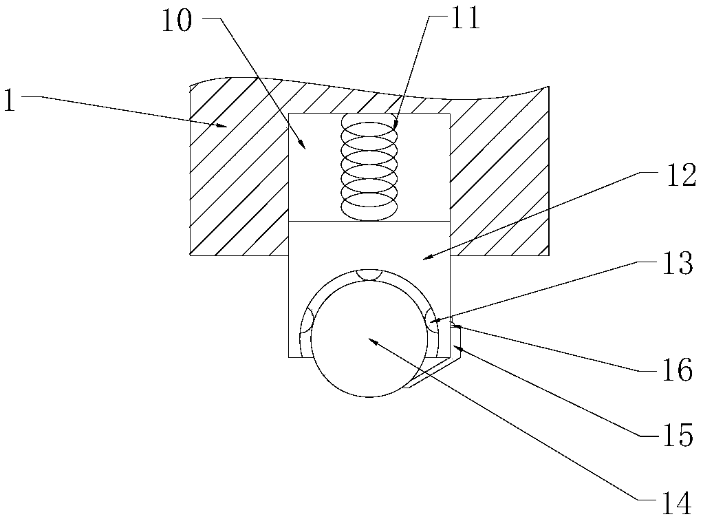
[0029] see Figure 1-5 As shown, a gluing equipment for assembling electronic components includes a storage cylinder 1, an automatic gluing mechanism, a gluing mechanism and a mounting mechanism;

[0030] The automatic glue pressing mechanism includes a rotating pin 2, a roller 3, a steel wire rope 4, a chute 5, a slider 6, an elastic rope 7, a ring 8 and a glue bottle 9, and two chutes 5 are arranged symmetrically inside the storage tube 1. , the inner top o...


PUM


Abstract

The invention discloses gluing equipment for assembling electronic components. The gluing equipment comprises a containing cylinder, rotating pins, rolling wheels, steel wire ropes, sliding grooves, sliding blocks, elastic ropes, circular rings, a glue bottle, grooves, springs, moving blocks, balls, a glue roller, a scraper, a spring hinge, vertical grooves, transverse grooves, metal sliding blocks, magnetic blocks and an end cover. According to the gluing equipment, the rolling wheels rotate to drive the rotating pins to rotate, the rotating pins rotate to enable the steel wire ropes to be wound around the annular side surfaces of the rotating pins, then the steel wire ropes pull the sliding blocks to move, the sliding blocks move to drive the circular rings to move, the circular rings move to drive the end cover to move, then the glue bottle is extruded to allow glue to be extruded out, the glue roller is rotated, the glue roller and the scraper slide relative to each other, then theglue dried on the glue roller is cleared, the end cover is installed inside the circular rings, then the metal sliding blocks move along the vertical grooves, then a user rotates the end cover, the end cover rotates to drive the metal sliding blocks to move along the transverse grooves to be attached to the magnetic blocks, then the metal sliding blocks are fixed inside the transverse grooves, and the installation of the end cover is realized.

Description

technical field [0001] The invention relates to a gluing equipment, in particular to a gluing equipment for assembling electronic components, and belongs to the technical field of assembling electronic components. Background technique [0002] Electronic components are components of electronic components and small electrical machines and instruments. They are often composed of several parts. Electronic components include: resistors, capacitors, potentiometers, electron tubes, radiators, electromechanical components, connectors, semiconductor discrete devices etc. [0003] The gluing equipment currently used for electronic component assembly has certain defects. It lacks the function of automatic glue extrusion, which causes the glue to not be squeezed out in time during the movement of the storage tube, resulting in uneven glue application, resulting in poor pasting effect, and lack of scraping. The glue function makes it inconvenient to clean the glue after it dries up on ...

Claims


Application Information

Patent Timeline
Patent Type & Authority Applications(China)
IPC IPC(8): B05C1/02B05C11/10B05C11/11B05B15/50
CPCB05C1/02B05B15/50B05C11/1002B05C11/11
Inventor 韩腾梁启红
Owner 郑州亨特利电子科技有限公司
Learn More