
Industrial waste gas processing device

A technology for processing devices and industrial waste gas, applied in the direction of removing smoke and dust, cleaning methods and utensils, chemical instruments and methods, etc., can solve the problems of troublesome intake pipe connection, troublesome wire fixing, inconvenient disassembly and maintenance, etc. Simple and efficient connection

Inactive Publication Date: 2020-01-03
杭州黄俊环保科技有限公司
View PDF0 Cites 1 Cited by
  • Summary
  • Abstract
  • Description
  • Claims
  • Application Information

AI Technical Summary

Problems solved by technology

[0004] The purpose of the present invention is to provide an industrial waste gas treatment device to solve the existing industrial waste gas treatment device proposed in the above background technology. It is troublesome to connect the waste gas delivery pipe to the intake pipe of the equipment. After the waste gas delivery pipe is placed on the intake pipe, It needs to be fixed and wound with iron wire to prevent the exhaust gas delivery pipe from slipping from the intake pipe, and the iron wire is more troublesome to fix, and it is not easy to disassemble and maintain.

Method used


Image

  • Industrial waste gas processing device
  • Industrial waste gas processing device
  • Industrial waste gas processing device

Examples


Embodiment

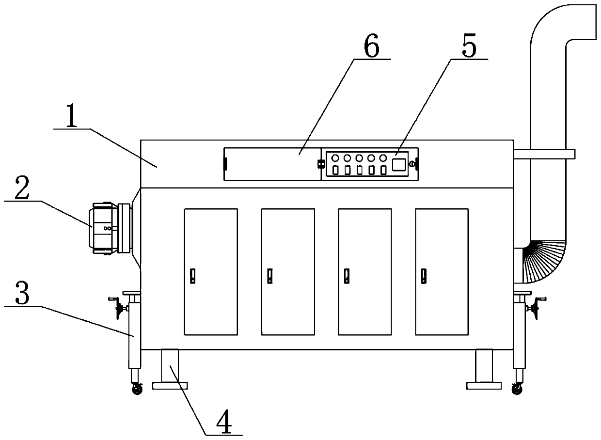
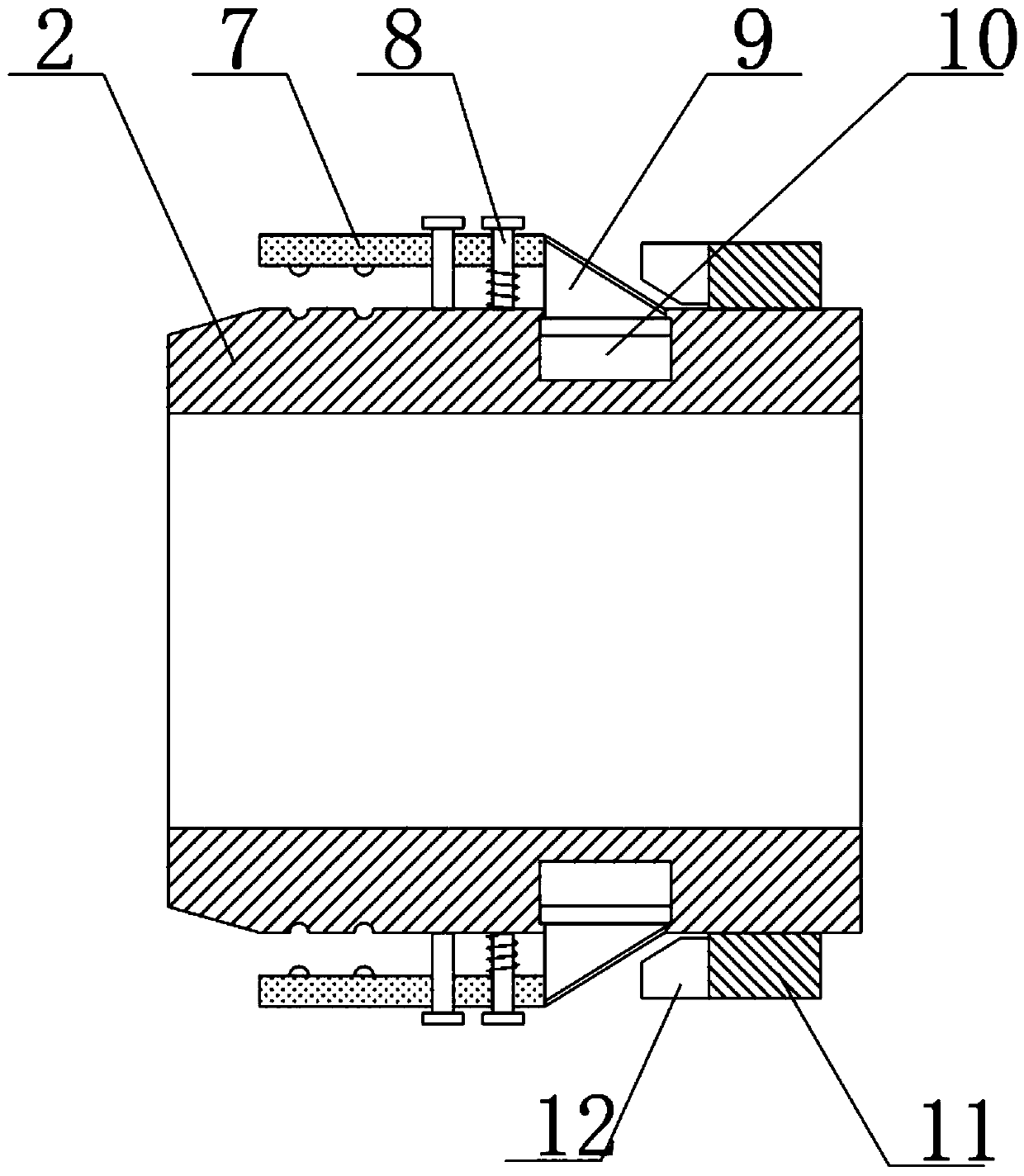
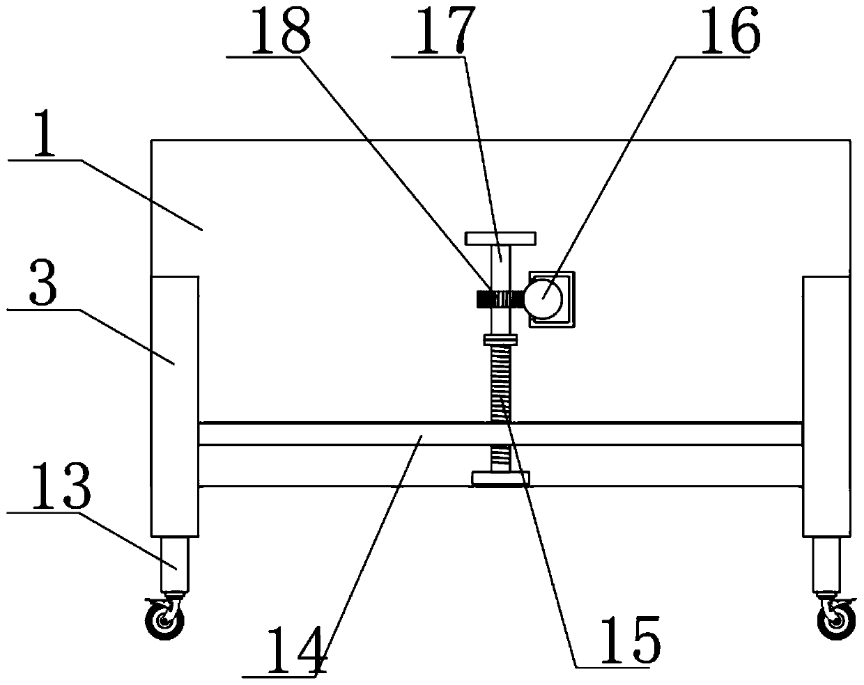
[0021] see Figure 1-Figure 4 , the present invention provides a technical solution: an industrial waste gas treatment device, including a device outer shell 1, the four corners of the lower surface of the device outer shell 1 are fixedly provided with support columns 4, and one end of the device outer shell 1 is provided with an air intake pipe 2, and the other end An exhaust pipe is provided, and the outer surface of the air intake pipe 2 is surrounded by evenly distributed sliding chambers 10, and a slider 9 is slid and embedded in the sliding chamber 10, and the end of the slider 9 protrudes from the sliding chamber 10, and the end One end of the intake pipe 2 is screwed with an internal thread ring 11, and one end of the internal thread ring 11 is welded and fixed with a circular ring 12. There is a gap of 2mm between the circular ring 12 and the intake pipe 2 to avoid The thread on the outer surface of the circular ring 12 and the intake pipe 2 is worn, the inner edge of...


PUM


Abstract

The invention discloses an industrial waste gas processing device. the industrial waste gas processing device comprises a device outer housing; the four corners of the lower surface of the device outer housing are each fixedly provided with a supporting column; one end of the device outer housing is provided with a gas charging pipe; the other end of the device outer housing is provided with an exhaust pipe; the outer surface of the gas charging pipe is provided with uniformly-distributed sliding chambers in a surrounding manner; each slider is slidably embedded inside the corresponding sliding chamber; the end part of each slider extends out of the corresponding sliding chamber; the end part of each extending end is fixedly provided with a pressing plate; one end of the gas charging pipeis provided with an internal thread ring in a thread screwing manner; one end of the internal thread ring is fixedly provided with a circular ring; the inner edge of the open end of the circular ringis set as a conical surface; the extending end of each slider is set as an arc-shaped inclined surface; by designing the sliders and the circular ring, a waste gas conveying pipe is hermetically arranged on the gas charging pipe in a sleeving manner; the waste gas conveying pipe can be quickly mounted or dismounted by rotating the internal thread ring; and the industrial waste gas processing device is simple to operate and convenient to use, improves the connection efficiency of gas pipes and can realize convenient clearing and maintenance by dismounting the gas pipes.

Description

technical field [0001] The invention belongs to the technical field of waste gas treatment, and in particular relates to an industrial waste gas treatment device. Background technique [0002] Exhaust gas treatment equipment mainly refers to equipment for treating industrial waste gas such as dust particles, flue gas and dust, odorous gas, and toxic and harmful gases generated in industrial sites. Common exhaust gas purification includes factory smoke and dust exhaust gas purification, workshop dust and exhaust gas purification, and organic waste gas purification. , Waste gas odor purification, acid-base waste gas purification, chemical waste gas purification, etc. [0003] In the existing industrial waste gas treatment devices, it is troublesome to connect the waste gas delivery pipe to the intake pipe of the equipment. After the waste gas delivery pipe is placed on the intake pipe, it needs to be fixed and wound with iron wires to prevent the waste gas delivery pipe from s...

Claims


Application Information

Patent Timeline
IPC IPC(8): B08B15/00B08B13/00
CPCB08B13/00B08B15/00
Inventor 黄俊
Owner 杭州黄俊环保科技有限公司
Learn More