
Building aluminum mold plate punching machine

A technology for aluminum templates and punching machines, which is applied in the direction of perforating tools, machine tools suitable for grinding workpiece edges, feeding devices, etc., which can solve the problem of reduced service life of devices, inability to further reduce punching impact force, and inability to grind aluminum templates and other issues to achieve the effect of maintaining the service life

Active Publication Date: 2019-03-29
GUANGDONG BOZHILIN ROBOT CO LTD
View PDF11 Cites 9 Cited by
  • Summary
  • Abstract
  • Description
  • Claims
  • Application Information

AI Technical Summary

Problems solved by technology

[0003] However, the construction aluminum formwork punching machines currently on the market cannot polish the punched part of the aluminum formwork after the punching is completed, resulting in the need for secondary processing; the impact force during punching cannot be further reduced, resulting in a long time for the device. After time is used, the service life of the device will be reduced; manual loading and unloading operations are required, resulting in a long loading and unloading time, which cannot improve work efficiency

Method used


Image

  • Building aluminum mold plate punching machine
  • Building aluminum mold plate punching machine
  • Building aluminum mold plate punching machine

Examples


Embodiment Construction

[0024] The following will clearly and completely describe the technical solutions in the embodiments of the present invention with reference to the accompanying drawings in the embodiments of the present invention. Obviously, the described embodiments are only some, not all, embodiments of the present invention. Based on the embodiments of the present invention, all other embodiments obtained by persons of ordinary skill in the art without making creative efforts belong to the protection scope of the present invention.

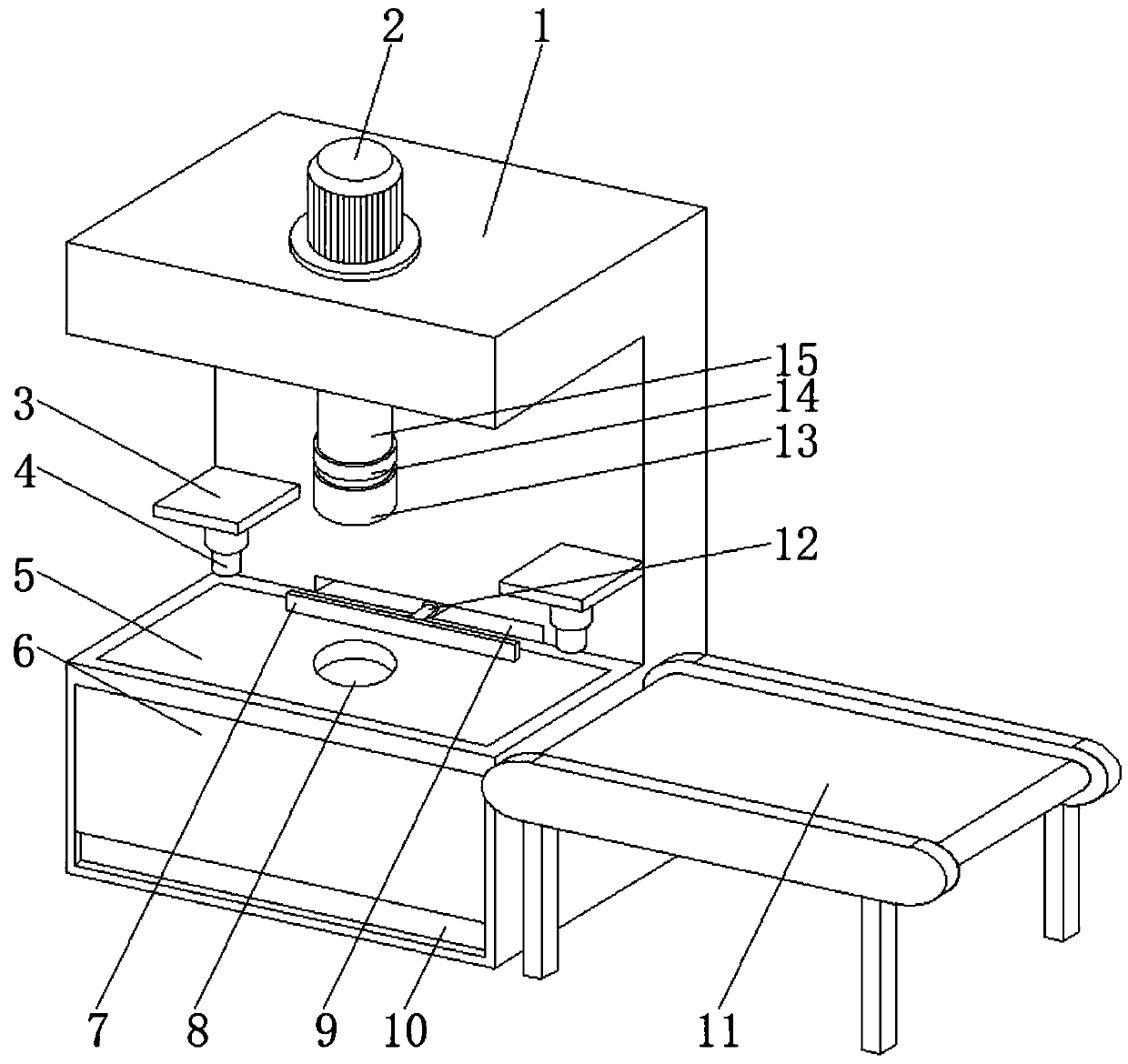
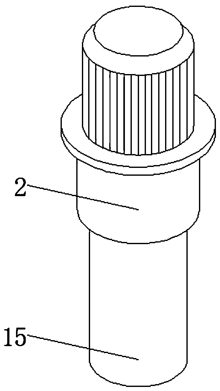
[0025] see Figure 1-8 , an embodiment of a building aluminum formwork punching machine provided by the present invention: a building aluminum formwork punching machine, including a punching machine main body 1, a servo pump 2 is installed on the top of the punching machine main body 1, and the punching machine main body The front surface of 1 is connected with a fixed plate 3, the front surface of the puncher main body 1 is provided with a bar-shaped groove 9...


PUM


Abstract

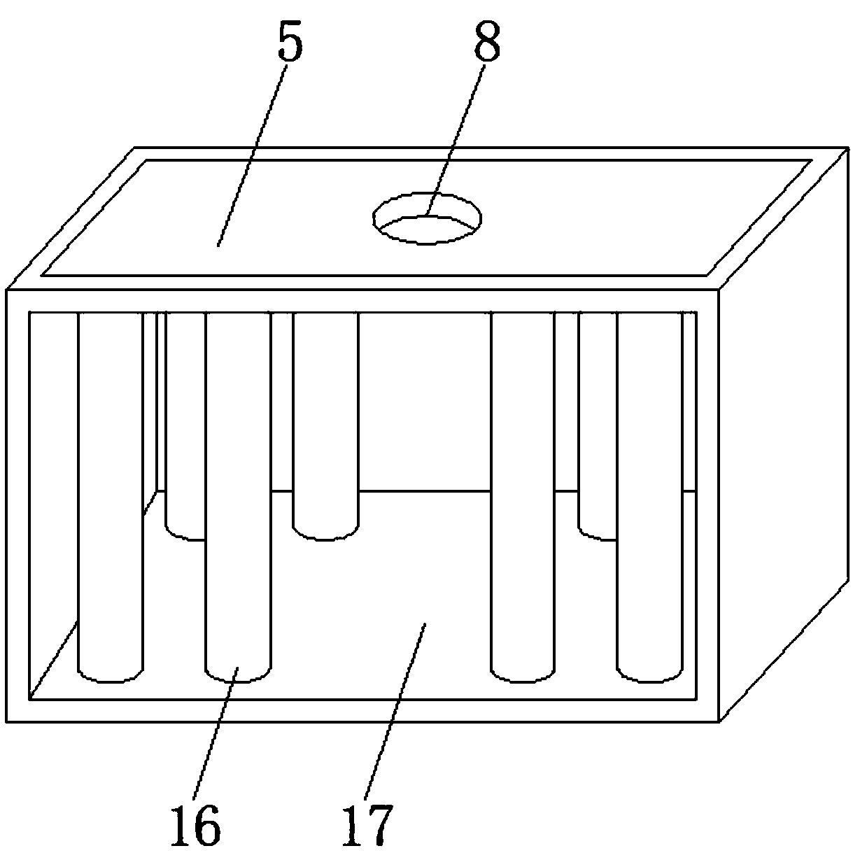
The invention discloses a building aluminum mold plate punching machine. The building aluminum mold plate punching machine comprises a punching machine body. A servo pump is installed at the top end of the punching machine body, fixing plates are connected with the front surface of the punching machine body, and a strip-shaped groove is formed in the portion, close to the bottom of the fixing plate, of the front surface of the punching machine body. A conveying belt is arranged on one side of the punching machine body, and a punching platform is connected with the inner wall of the punching machine body. According to the building aluminum mold plate punching machine, a servo motor and a polishing piece are arranged, the servo motor drives the polishing piece to rotate through a rotating shaft and a rotating plate, the polishing piece polishes a punching portion of an aluminum mold plate, and therefore the problem that after punching is accomplished, secondary operation needs to be conducted is effectively solved. Due to the fact that springs, connecting plates and bearing columns are arranged, when punching is conducted, the aluminum mold plate transmits the impact force to the punching platform, the punching platform transmits the impact force to the springs, the connecting plates and the bearing columns, the impact force can be dispersed, and the service life of the device iseffectively prolonged.

Description

technical field [0001] The invention relates to the field of punching machines, in particular to a punching machine for building aluminum templates. Background technique [0002] Punching machine is the active part of sheet processing, stamping, molding, embossing, etc., which forces metal into the mold. It is suitable for leather, cowhide, artificial leather, plastic, PU, ​​EVA, PVC, various cloth, paper, and leather accessories. , Punching processing of shoe uppers, decorative pieces, curtains, car leather chairs, etc. [0003] However, the construction aluminum formwork punching machines currently on the market cannot polish the punched part of the aluminum formwork after the punching is completed, resulting in the need for secondary processing; the impact force during punching cannot be further reduced, resulting in a long time for the device. After time is used, the service life of the device will be reduced; manual loading and unloading operations are required, result...

Claims


Application Information

Patent Timeline
Patent Type & Authority Applications(China)
IPC IPC(8): B21D28/34B21D43/02B24B9/04
CPCB21D28/34B21D43/027B24B9/04
Inventor 孙军杨泓斌李义鹏陈明亚肖培春
Owner GUANGDONG BOZHILIN ROBOT CO LTD
Learn More