
Novel method for stamping back door avoiding part at rear part of car top cover product
A new method, the technology of the top cover, applied in the direction of vehicle parts, transportation and packaging, can solve the problems of shaping slippage and wrinkling, and achieve the effect of reducing machine tool time, shortening debugging time, and reducing mold development costs.
- Summary
- Abstract
- Description
- Claims
- Application Information
AI Technical Summary
Problems solved by technology
Method used
Image

Examples
Embodiment
[0019] A new stamping method for the back door avoidance part of the car top cover product, which sequentially includes: OP10 drawing, OP20 trimming and punching side shaping, OP30 trimming and punching flanging and shaping, and OP40 trimming and punching side punching and rollover side.
[0020] The side shaping of the back door avoidance part at the back of the top cover is carried out by OP20, and the structure diagram of the mold used is as follows Figure 4 As shown, including the positive feeder 1, the side shaping insert 2, the side presser 3 and the lower die insert 4, etc., the processing and debugging steps of the shaping die of the new stamping process method are the same as the existing scheme, and remain unchanged.
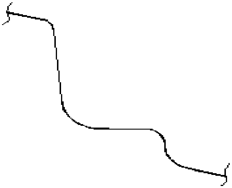
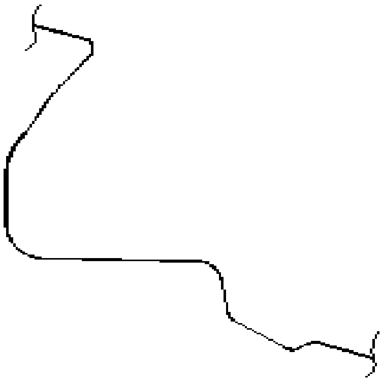
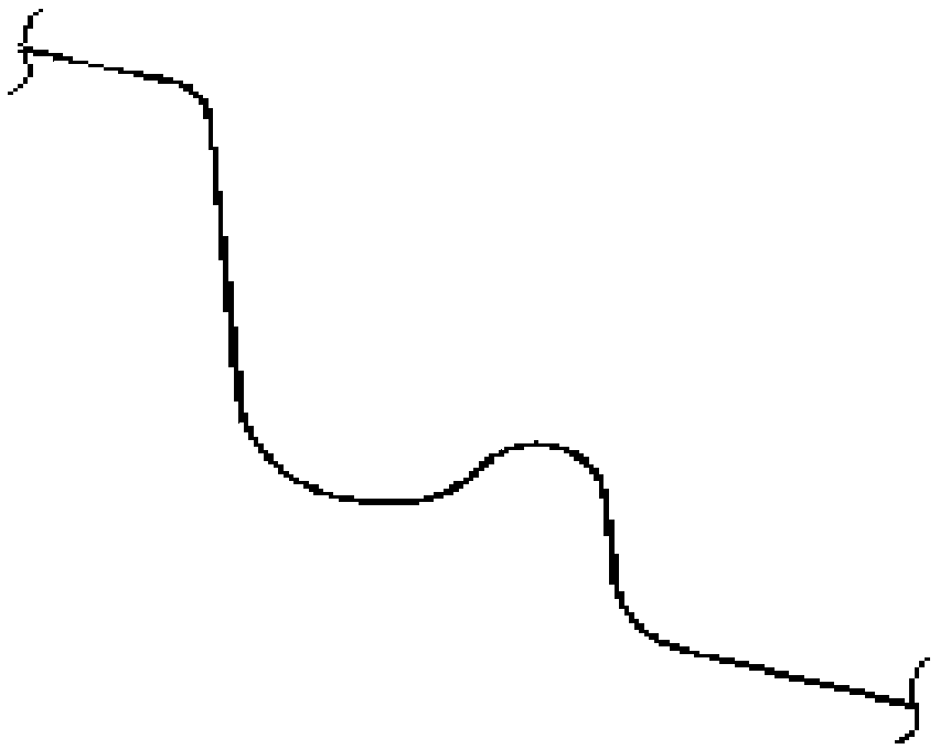
[0021] The main change point is OP10: that is, the shape is added to the position of the drawing die punch in the side shaping area (see image 3 ), to increase the length of the plastic surgery area, so as to store enough materials for the side plas...
PUM
| Property | Measurement | Unit |
|---|---|---|
| length | aaaaa | aaaaa |
Abstract
Description
Claims
Application Information