Novel stable welding machine

A welding machine, stable technology, applied in welding equipment, auxiliary welding equipment, welding/cutting auxiliary equipment, etc., can solve the problems of unstable welding quality, rough welding parts quality, rising manufacturing cost, etc., to achieve the welding process. Simple and convenient, meet the needs of welding, use a wide range of effects

Inactive Publication Date: 2019-03-29
扬州市诚智自动化装备有限公司
View PDF0 Cites 0 Cited by
  • Summary
  • Abstract
  • Description
  • Claims
  • Application Information

AI Technical Summary

Problems solved by technology

[0002] Many welding operations require manpower for welding. The quality of welding is not very stable when welding by manpower. The quality of many welding parts is too rough, which affects the welding quality of parts. When welding with a lot of manpower It will cause the continuous increase of manufacturing cost, which will affect the sales of workpieces. Therefore, many enterprises are using welding machines. Welding machines can make welding more efficient, and can carry out continuous high-frequency welding. The welding effect and good quality

Method used


Image

  • Novel stable welding machine

Examples


Embodiment 1

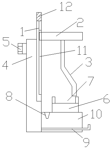
[0012] A new type of stable welding machine is provided with a movable rod 1, a top cover 2 is arranged on the movable rod 1, a movable welding head 3 is arranged below the ejector rod 1, and beside the movable rod 1 A support rod 4 is provided, and a motor 5 is arranged on the support rod 4. The motor 5 drives the movable welding head 3 to move, and the bottom end of the support rod 4 is provided with a processing table 6. During the processing A positioning plate 7 is arranged inside the table 6 , and chip relief grooves 8 are arranged on both sides of the processing table 6 .

[0013] A blanking plate 9 is arranged under the chip relief groove 8, and the blanking plate 9 is located at the lower end of the processing table.

[0014] A blanking cavity 10 is arranged under the processing table 6, and the blanking plate 9 is movably inserted into the blanking cavity 10.

[0015] The movable rod 1 is provided with a movable groove 11, and the top cover 2 is embedded in the mova...

Embodiment 2

[0017] A new type of stable welding machine is provided with a movable rod 1, a top cover 2 is arranged on the movable rod 1, a movable welding head 3 is arranged below the ejector rod 1, and beside the movable rod 1 A support rod 4 is provided, and a motor 5 is arranged on the support rod 4. The motor 5 drives the movable welding head 3 to move, and the bottom end of the support rod 4 is provided with a processing table 6. During the processing A positioning plate 7 is arranged inside the table 6 , and chip relief grooves 8 are arranged on both sides of the processing table 6 .

[0018] A blanking plate 9 is arranged under the chip relief groove 8, and the blanking plate 9 is located at the lower end of the processing table.

[0019] A blanking cavity 10 is arranged under the processing table 6, and the blanking plate 9 is movably inserted into the blanking cavity 10.

[0020] The movable rod 1 is provided with a movable groove 11, and the top cover 2 is embedded in the mova...

Embodiment 3

[0023] A new type of stable welding machine is provided with a movable rod 1, a top cover 2 is arranged on the movable rod 1, a movable welding head 3 is arranged below the ejector rod 1, and beside the movable rod 1 A support rod 4 is provided, and a motor 5 is arranged on the support rod 4. The motor 5 drives the movable welding head 3 to move, and the bottom end of the support rod 4 is provided with a processing table 6. During the processing A positioning plate 7 is arranged inside the table 6 , and chip relief grooves 8 are arranged on both sides of the processing table 6 .

[0024] A blanking plate 9 is arranged under the chip relief groove 8, and the blanking plate 9 is located at the lower end of the processing table.

[0025] A blanking cavity 10 is arranged under the processing table 6, and the blanking plate 9 is movably inserted into the blanking cavity 10.

[0026] The movable rod 1 is provided with a movable groove 11, and the top cover 2 is embedded in the mova...


PUM


Abstract

The invention relates to a novel stable welding machine. A moving rod is arranged. A top cover is arranged on the moving rod. A movable welding connector is arranged under the top rod. A supporting rod is arranged beside the moving rod. A motor is arranged on the supporting rod. The motor drives the movable welding connector to move. A machining table is arranged at the bottom end of the supporting rod. The machining table is internally provided with a positioning disc. Debris removing grooves are formed in two sides of the machining table. The moving rod is arranged on the welding machine todrive a welding head to move up and down, and therefore workpieces with different heights can be welded. Workpiece welding procedures are more simple and convenient, and requirements for welding workpieces with different height can be met. Application of the welding machine is wide. A material falling plate is arranged below the machining table, and therefore debris can fall onto the material falling plate for processing.

Description

technical field [0001] The invention relates to a welding device, in particular to a novel stable welding machine. Background technique [0002] Many welding operations require manpower for welding. The quality of welding is not very stable when welding by manpower. The quality of many welding parts is too rough, which affects the welding quality of parts. When welding with a lot of manpower It will cause the continuous increase of manufacturing cost, which will affect the sales of workpieces. Therefore, many enterprises are using welding machines. Welding machines can make welding more efficient, and can carry out continuous high-frequency welding. The welding effect and good quality. Contents of the invention [0003] The purpose of the present invention is to provide a new type of stable welding machine with stable welding and reasonable structure. [0004] The technical solution of the present invention is: a new type of stable welding machine, provided with a movabl...

Claims


Application Information

Patent Timeline
Patent Type & Authority Applications(China)
IPC IPC(8): B23K37/02B23Q11/00
CPCB23K37/0211B23K37/0247B23Q11/0042
Inventor 陈后庆施道伟高优
Owner 扬州市诚智自动化装备有限公司
Why Eureka
Try Eureka