Robot wrist assembly debugging device

A robot and wrist technology, applied in the field of robot wrist assembly and debugging device, can solve the problems of low measurement efficiency, unsuitable for large-load robots, and reduced assembly accuracy, and achieve accurate and reliable measurement data, good assembly effect, and improved production efficiency.

Pending Publication Date: 2019-03-29
CHONQING HUASHU ROBOT CO LTD
View PDF7 Cites 0 Cited by
  • Summary
  • Abstract
  • Description
  • Claims
  • Application Information

AI Technical Summary

Problems solved by technology

[0002] When the traditional industrial robot wrist adopts nested bevel gear transmission, it is necessary to adjust the installation distance of the bevel gear. The usual method is to add a shim of corresponding thickness to the bevel gear mounting surface to adjust, but how to determine the thickness of the shim to use is It is a cumbersome and inefficient process; not only does it need to measure the installation size of the bevel gear, which is a machine-added part of the robot wrist, but also requires the use of a three-coordinate measuring instrument due to the irregular shape of the robot wrist parts, and the measurement efficiency is low; and to measure the installation distance of the bevel gear, it is necessary Special-purpose gear measuring equipment is expensive and not suitable for small-batch and large-load robot production. It also requires multiple disassembly and assembly of wrist parts, which is labor-intensive and low in efficiency. At the same time, multiple disassembly and assembly are likely to reduce assembly accuracy and other issues.

Method used


Image

  • Robot wrist assembly debugging device
  • Robot wrist assembly debugging device

Examples


Embodiment Construction

[0027] The principles and features of the present invention are described below in conjunction with the accompanying drawings, and the examples given are only used to explain the present invention, and are not intended to limit the scope of the present invention.

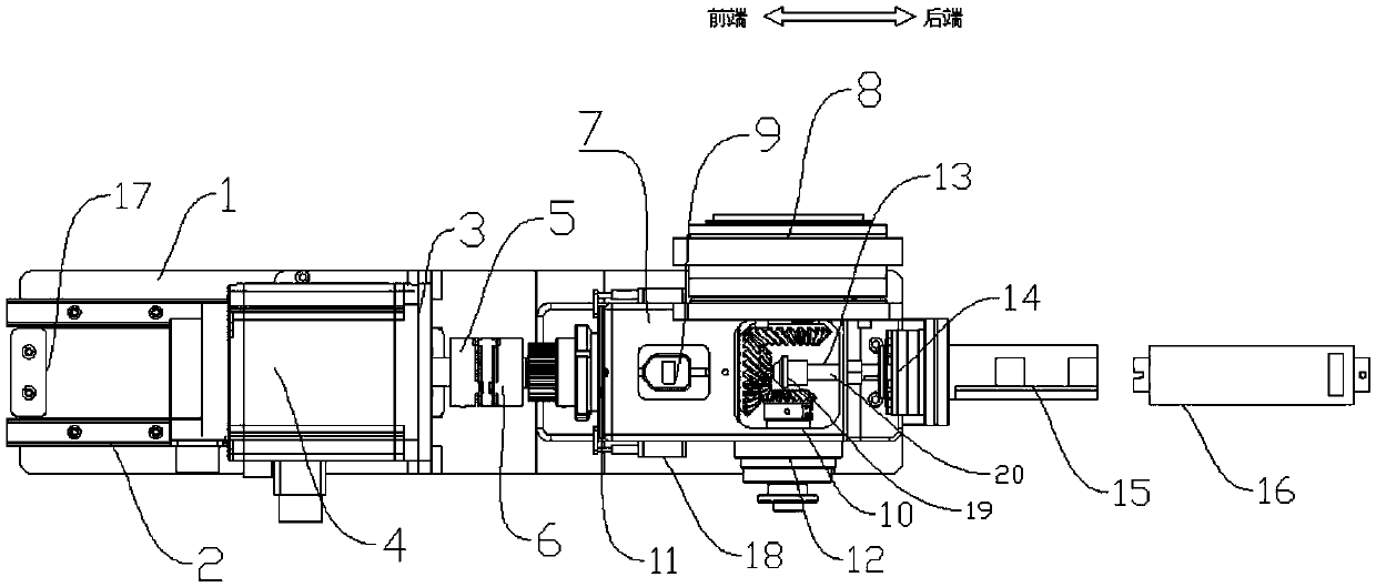
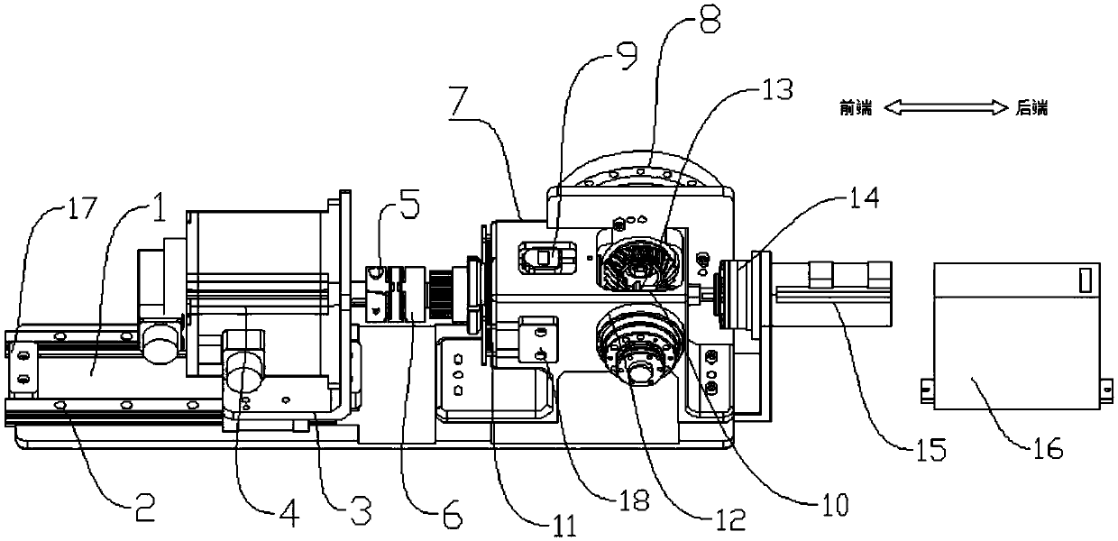
[0028] Such as figure 1 As shown, a robot wrist assembly and debugging device includes a mounting substrate 1, a high-precision guide rail 2, a motor mounting plate 3, a driving motor 4, a transmission component, a component bracket 7, a first reducer 8, a displacement sensor 9, and a displacement adjustment thimble 13. The driving device, wherein,

[0029] The high-precision guide rail 2 is fixedly installed on the front end of the installation substrate 1, the driving motor 4 is movably installed on the high-precision guide rail 2 through the motor mounting plate 3, and the driving motor 4 is connected with the transmission Component transmission connection, the drive motor 4 slides on the high-precision guide ra...


PUM


Abstract

The invention discloses a robot wrist assembly debugging device. The robot wrist assembly debugging device comprises a mounting substrate, a high-precision guide rail, a motor mounting plate, a driving motor, a transmission module, a part bracket, a first speed reducer, a displacement sensor, a displacement adjusting thimble and a driving device; the high-precision guide rail is mounted on the left side of the mounting substrate; the driving motor is mounted on the high-precision guide rail through the motor mounting plate, and is in transmission connection with the transmission module; the part bracket is fixedly mounted on the right side of the mounting substrate, and is provided with a first mounting part and a second mounting part; the first speed reducer is arranged on the back side of the part bracket; a through hole is formed in the part bracket; and the displacement adjusting thimble is arranged on the right side of the part bracket, and is in transmission connection with the driving device. The robot wrist assembly debugging device can guarantee precise and reliable measurement data to achieve excellent assembly effect, is simple in operation, and greatly improves the production efficiency.

Description

technical field [0001] The invention relates to the field of robot installation and debugging, in particular to a robot wrist assembly and debugging device. Background technique [0002] When the traditional industrial robot wrist adopts nested bevel gear transmission, it is necessary to adjust the installation distance of the bevel gear. The usual method is to add a shim of corresponding thickness to the bevel gear mounting surface to adjust, but how to determine the thickness of the shim to use is It is a cumbersome and inefficient process; not only does it need to measure the installation size of the bevel gear, which is a machine-added part of the robot wrist, but also requires the use of a three-coordinate measuring instrument due to the irregular shape of the robot wrist parts, and the measurement efficiency is low; and to measure the installation distance of the bevel gear, it is necessary Special-purpose gear measuring equipment is expensive and not suitable for smal...

Claims


Application Information

Patent Timeline
Patent Type & Authority Applications(China)
IPC IPC(8): B25J19/00
CPCB25J19/00B25J19/0095
Inventor 范秋垒杨伦
Owner CHONQING HUASHU ROBOT CO LTD
Why Eureka
Try Eureka