Positioning grooving equipment for plastic boards

A technology for slotting equipment and plastic plates, applied in metal processing and other directions, can solve the problems of unrecoverable waste, poor positioning effect of plastic plates, and plate shaking, etc., to prevent damage, improve overall practical performance, and improve practical performance.

Pending Publication Date: 2019-03-29
BINZHOU UNIV
View PDF1 Cites 4 Cited by
  • Summary
  • Abstract
  • Description
  • Claims
  • Application Information

AI Technical Summary

Problems solved by technology

[0003] Existing such as patent No. CN106827001A a kind of plastic plate slotting device, the upper surface of the workbench is provided with a horizontal pallet, the surface of the horizontal pallet is processed with a rectangular groove, when the plastic plate is placed on the horizontal pallet, the horizontal The linear motor in the mounting block on the vertical top plate on both sides of the supporting plate will expand and contract horizontally, the L-shaped top plate at the telescopic end will move, and the No. 2 linear motor on the L-shaped top plate will expand and contract horizontally, and the top plate at the telescopic end will move to withstand the plastic plate , the rear surface of the plastic plate bears against the No. 2 vertical top plate, and then the linear motors on both sides and the No. 2 linear motor expand and contract to clamp the plastic plate. The electric trolley slides on the slide rail, and then there is a mounting plate on

Method used


Image

  • Positioning grooving equipment for plastic boards
  • Positioning grooving equipment for plastic boards
  • Positioning grooving equipment for plastic boards

Examples


Example Embodiment

[0032] The technical solutions of the present invention will be clearly and completely described below in conjunction with the accompanying drawings. Obviously, the described embodiments are part of the embodiments of the present invention, rather than all of them.

[0033] The components of the embodiments of the present invention generally described and shown in the drawings herein may be arranged and designed in various different configurations. Therefore, the following detailed description of the embodiments of the present invention provided in the accompanying drawings is not intended to limit the scope of the claimed invention, but merely represents selected embodiments of the present invention.

[0034] Based on the embodiments of the present invention, all other embodiments obtained by those of ordinary skill in the art without creative work shall fall within the protection scope of the present invention.

[0035] In the description of the present invention, it should be note...


PUM


Abstract

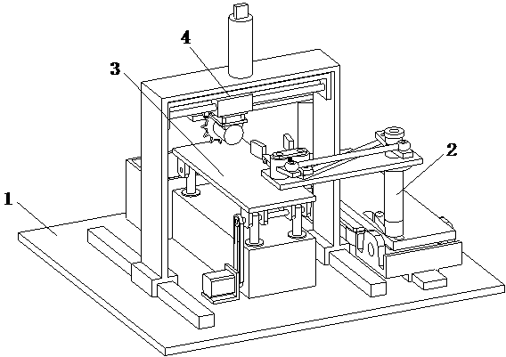
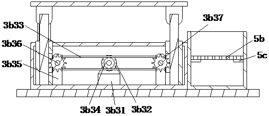
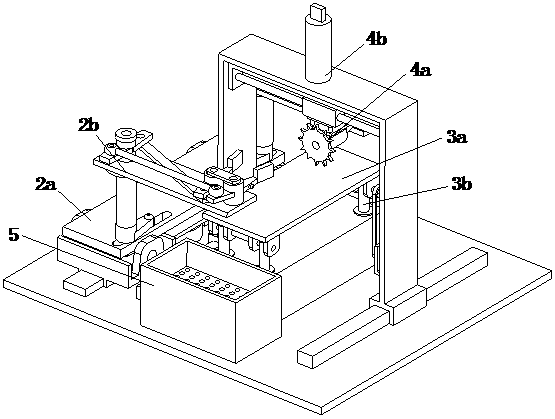
The invention discloses positioning grooving equipment for plastic boards, and belongs to the field of plastic component processing equipment. The positioning grooving equipment comprises a base plate, a positioning device, a lifting device, a grooving device and a recycling device, the positioning device comprises a bearing assembly, two clamping assemblies and a driving assembly, the driving assembly is arranged inside the bearing assembly, the two clamping assemblies are symmetrically arranged on the bearing assembly, the front ends of the two clamping assemblies extend to the part above the lifting device, the lifting device comprises a bearing assembly, a lifting assembly and a linking assembly, the linking assembly is installed at the top of the base plate, the top end of the linkingassembly is in drive connection with the bearing assembly, the lifting assembly is located under the bearing assembly, and the grooving device comprises a groove cutting assembly and a moving assembly. The positioning device and the grooving device are matched to realize grooving in two faces of the plastic boards and grooving in different positions, demand for grooving machining of plastic boards with different sizes can be met, and accordingly overall practicability is improved.

Description

technical field [0001] The invention relates to the field of plastic parts processing equipment, in particular to a positioning and slotting equipment for plastic plates. Background technique [0002] Plastic is a class of plastic synthetic polymer materials. The plastic board industry is the pillar industry of my country's light industry. At present, my country's plastic board industry is facing opportunities for development, but it will also encounter many challenges. This needs to be dominated by the market and enterprises, and the government is providing policy guidance to move towards a plastic board power. At present, in the process of plastic plate processing, for the convenience of later connection or actual production needs, grooving its surface is an indispensable step. [0003] Existing such as patent No. CN106827001A a kind of plastic plate slotting device, the upper surface of the workbench is provided with a horizontal pallet, the surface of the horizontal pa...

Claims


Application Information

Patent Timeline
IPC IPC(8): B26D1/18B26D3/06B26D7/18B26D7/02
CPCB26D1/185B26D3/065B26D7/015B26D7/02B26D7/18
Inventor 姚延立
Owner BINZHOU UNIV
Why Eureka
Try Eureka