Tightener of sewing machine

A thread tensioner and sewing machine technology, applied in the field of sewing machines, can solve problems such as poor reproducibility, unstable thread tension adjustment, hinder sewing efficiency and improve sewing stability, and achieve the effect of improving adjustment efficiency

Pending Publication Date: 2019-03-29
吴江市宝鑫机械有限公司
View PDF0 Cites 0 Cited by
  • Summary
  • Abstract
  • Description
  • Claims
  • Application Information

AI Technical Summary

Problems solved by technology

[0002] Usually, the sewing machine combines the upper thread and the lower thread to form seams on the fabric through the cooperation of the needle above the needle plate and the rotary hook below the needle plate. When the sewing machine is working, it is necessary to adjust the tension of the upper thread and the lower thread to ensure the seam Smooth and beautiful. At present, the tension of the upper thread of the sewing machine is mainly adjusted by the thread tensioner that works with the nut and the spring. By turning the nut, the spring is compressed, and the two compressions of the thread tensioner used to clamp the upper thread are reduced. The distance between the pieces can be used to adjust the tension of the upper thread, but the contact surface between the two pressing pieces is usually relatively smooth, and the sutures are very thin. It is difficult to ensure that the pressure does not slip when pressing close together, and it is easy to adjust the thread tension. Unstable, and when the upper thread needs to be replaced, it can only be replaced by turning the nut. After the replacement, the nut must be turned again to adjust the upper thread arrangement. The adjustment amount is not easy to control and the reproducibility is poor. Repeatedly tightening the adjustment button to find and obtain the best tension hinders the further improvement of sewing efficiency and also requires the sewing stability of the product

Method used


Image

  • Tightener of sewing machine
  • Tightener of sewing machine
  • Tightener of sewing machine

Examples


Embodiment Construction

[0018] The preferred embodiments of the present invention will be described below in conjunction with the accompanying drawings. It should be understood that the preferred embodiments described here are only used to illustrate and explain the present invention, and are not intended to limit the present invention.

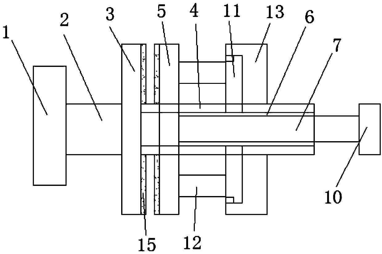
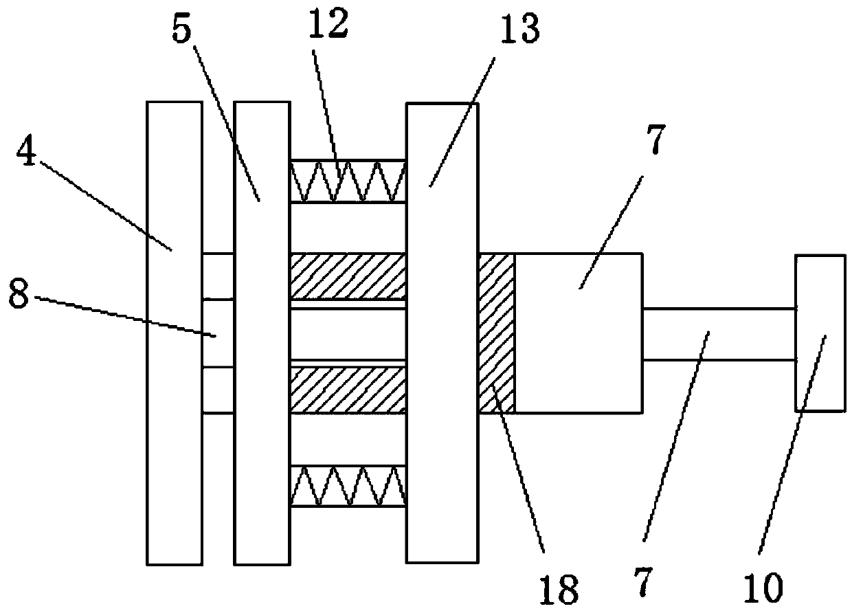
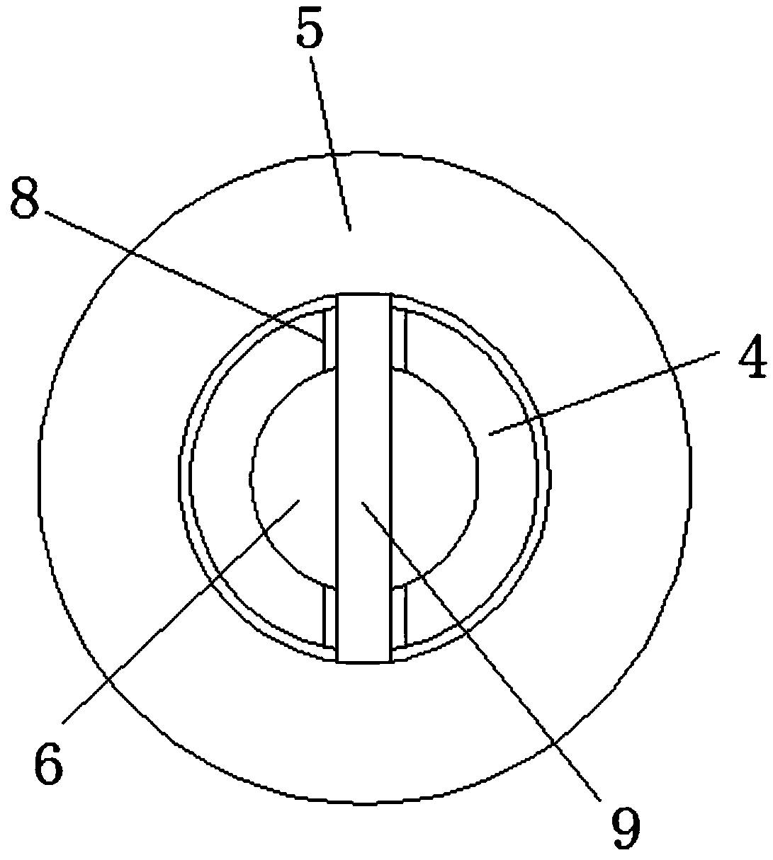
[0019] see Figure 1-Figure 4 , the present invention provides a technical solution:

[0020] A thread tensioner for a sewing machine, comprising a mounting plate 1, the right side of the mounting plate 1 is fixedly connected with a fixed rod 2, the right side of the fixed rod 2 is fixedly connected with a fixed splint 3, and the right side of the fixed splint 3 is connected with a Adjusting rod 4, the outer side of the adjusting rod 4 is provided with a movable splint 5, the inner cavity of the adjusting rod 4 is provided with a through hole 6, the through hole 6 is provided with a drawer rod 7, symmetrically opened on the adjusting rod 4 There is a guide groove 8...


PUM


Abstract

The invention relates to a tightener of a sewing machine. The tightener comprises a mounting plate. A fixed bar is fixedly connected to the right side of the mounting plate, a fixed clamping plate isfixedly connected to the right side of the fixed bar, an adjusting rod is connected to the right side of the fixed clamping plate, a movable clamping plate is arranged on the outer side of the adjusting rod in a sleeving manner, a through hole is formed in an inner cavity of the adjusting rod, the drawing rod is arranged in the through hole, guide slots are symmetrically formed in the adjusting rod, a connecting rod is fixedly arranged in the movable clamping plate, the connecting rod penetrates through the guide slots, the left end of the drawing rod is connected to the connecting rod, the right end of the drawing rod extends out of the adjusting rod and is fixedly connected to a handle, a fastening plate is arranged on the right side of the movable clamping plate, the movable clamping plate is connected to the fastening plate through a spring, and the outside of the adjusting rodis sleeved with the fastening plate. The stability of the tightener to upper thread tension adjustment isimproved, the control force of the upper thread is enhanced, and meanwhile, the upper thread can be replaced without changing the tension of the tightener, so that the seam stitch is smooth and attractive.

Description

technical field [0001] The invention relates to a thread tensioner for a sewing machine, which belongs to the technical field of sewing machines. Background technique [0002] Usually, the sewing machine combines the upper thread and the lower thread to form seams on the fabric through the cooperation of the needle above the needle plate and the rotary hook below the needle plate. When the sewing machine is working, it is necessary to adjust the tension of the upper thread and the lower thread to ensure the seam Smooth and beautiful. At present, the tension of the upper thread of the sewing machine is mainly adjusted by the thread tensioner that works with the nut and the spring. By turning the nut, the spring is compressed, and the two compressions of the thread tensioner used to clamp the upper thread are reduced. The distance between the pieces can be used to adjust the tension of the upper thread, but the contact surface between the two pressing pieces is usually relativ...

Claims


Application Information

Patent Timeline
IPC IPC(8): D05B47/00
CPCD05B47/00
Inventor 朱平
Owner 吴江市宝鑫机械有限公司
Why Eureka
Try Eureka