Driving structure for sinking-method rotation-type vertical shaft tunnelling machine

A driving structure and roadheader technology, which is applied in the direction of drilling driving devices, shaft equipment, and sinking in boreholes. It can solve problems that affect construction quality, cannot achieve full-section cutting, and cannot adjust the trajectory of motion, and achieve repeated crushing. low rate effect

Pending Publication Date: 2019-03-29
CHINA CONSTR UNDERGROUND SPACE +1
View PDF0 Cites 4 Cited by
  • Summary
  • Abstract
  • Description
  • Claims
  • Application Information

AI Technical Summary

Problems solved by technology

The upper end of the shaft is connected to the ground, and the lower end of the shaft is connected to the roadway or tunnel. The shaft excavation is the construction process of digging the shaft (also known as the shaft) vertically downward from the ground; when the driving device of the existing shaft boring machine drives the cutter head to cut the section, The effect of full-section cutting cannot be achieved, and the motion trajectory cannot be adjusted, and the adhesive attached to the tool seriously affects the construction quality

Method used


Image

  • Driving structure for sinking-method rotation-type vertical shaft tunnelling machine
  • Driving structure for sinking-method rotation-type vertical shaft tunnelling machine

Examples


Embodiment Construction

[0015] The present invention can be explained in detail through the following examples, and the purpose of disclosing the present invention is to protect all technical improvements within the scope of the present invention.

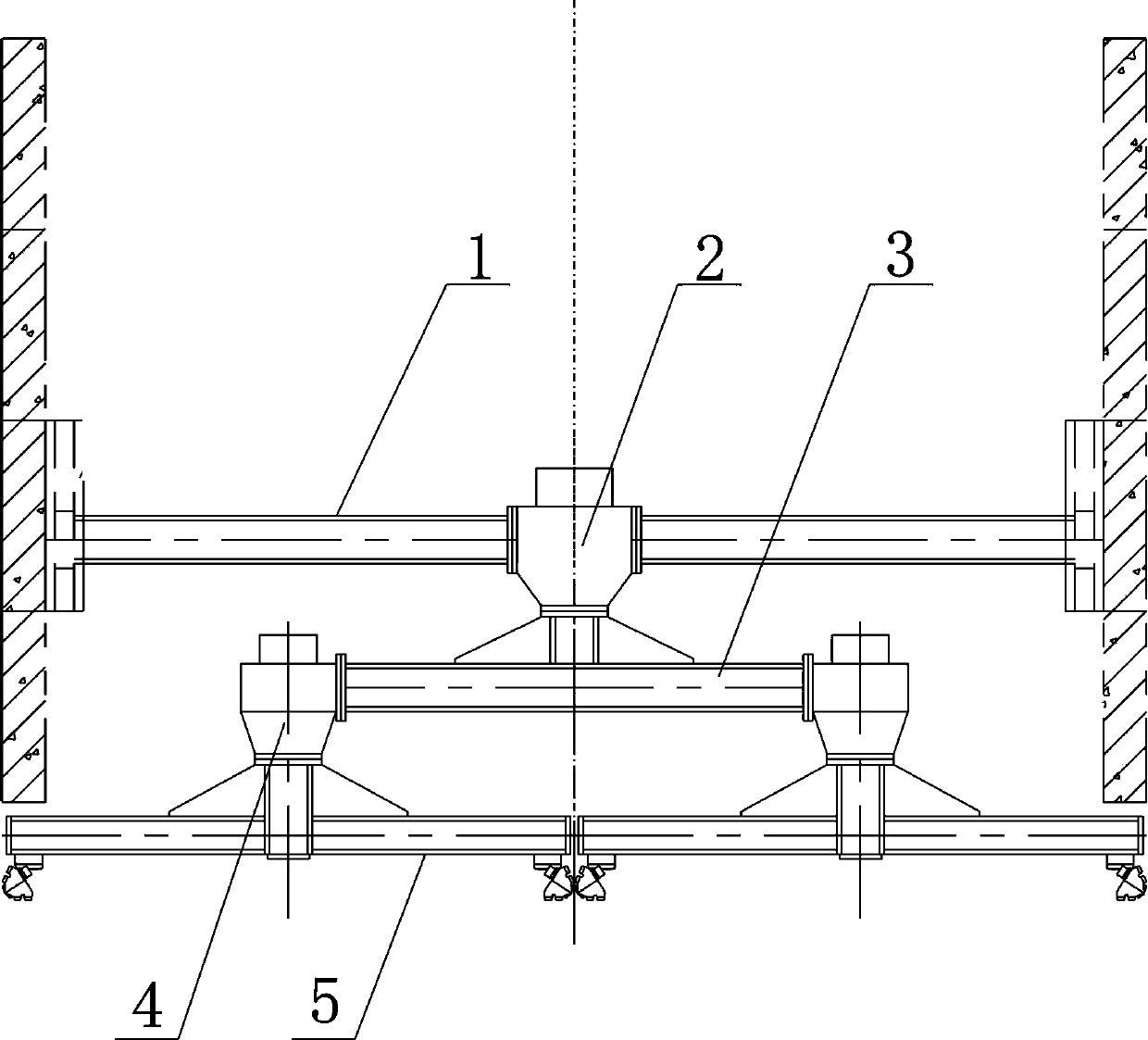
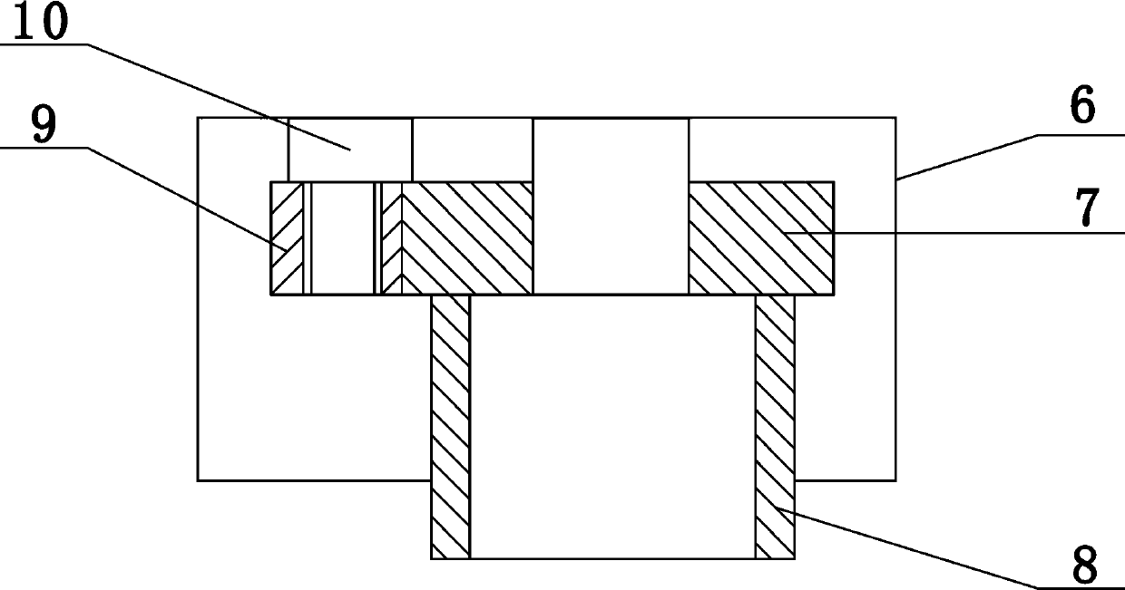
[0016] combined with Figure 1-2 The driving structure for the submerged rotary shaft boring machine includes a drilling arm 3 and a driving mechanism. The driving mechanism includes a main driving device 2 and a secondary driving device 4 of the same structure. The outside of the main driving device 2 is connected to the shaft boring machine. On the drilling frame 1, the bottom of the main driving device 2 is connected with a drilling arm 3, and a plurality of secondary driving devices 4 are arranged at intervals on the drilling arm 3. The main driving device 2 includes a first outer box body 6, and is installed on the first The main drive motor 10 and the first gear box in the outer box body 6, the first outer box body 6 is installed in the middle part ...


PUM


Abstract

The invention discloses a driving structure for a sinking-method rotation-type vertical shaft tunnelling machine and relates to a driving structure. The driving structure comprises a tunnelling rack,a drilling arm and a driving mechanism, the driving mechanism comprises a main driving device and multiple sub driving devices, the main driving device and the sub driving devices are of the same structure, and the tunnelling rack is connected to the exterior of the main driving device; the drilling arm is connected to the lower portion of the main driving device, the sub driving devices are arranged on the drilling arm at intervals, the main driving device comprises a first outer box, a main driving motor and a first gear box, the main driving motor and the first gear box are installed in thefirst outer box, and the first outer box is fixedly installed in the middle of the tunnelling rack; an output shaft of the main driving motor is connected with a drive gear of the first gear box, andthe lower portion of a driven gear of the first gear box extends out of the first outer box and is connected with the middle of the drilling arm; two or more sub driving devices are installed on thedrilling arm. According to the driving structure, through rotation of the drilling arm and a drilling tool body, all-cross-section tunnelling and all-cross-section cutting are achieved, the rotation speed and rotation direction of the drilling arm and the drilling tool body can be adjusted, and the driving structure is suitable for different geological conditions.

Description

technical field [0001] The invention relates to a driving structure, in particular to a driving structure for a rotary shaft boring machine with a subsidence method. Background technique [0002] It is well known that with the development of the national economy, the construction of urban rail transit and the construction of urban underground pipe corridors have developed rapidly in recent years; in the construction of underground projects, such as shield starting and receiving shafts, mining shafts, tunnel ventilation shafts, underground fortification shafts, In the construction of underground parking lots, mine roadways, traffic tunnels and other underground projects, in order to ensure the smooth progress of the construction, it is necessary to excavate shafts for transporting materials and ventilation. The upper end of the shaft is connected to the ground, and the lower end of the shaft is connected to the roadway or tunnel. The shaft excavation is the construction proce...

Claims


Application Information

Patent Timeline
Patent Type & Authority Applications(China)
IPC IPC(8): E21D1/06E21B4/04
CPCE21D1/06E21B4/04
Inventor 郑立宁王占军荆伟苗军克朱文汇孟永红胡熠赵智峰胡怀仁胡国辉
Owner CHINA CONSTR UNDERGROUND SPACE
Why Eureka
Try Eureka